ESP8266 Witty Cloud Behavior

I'm using an ESP8266 Witty Cloud board to drive a 28BYJ-48 stepper motor.
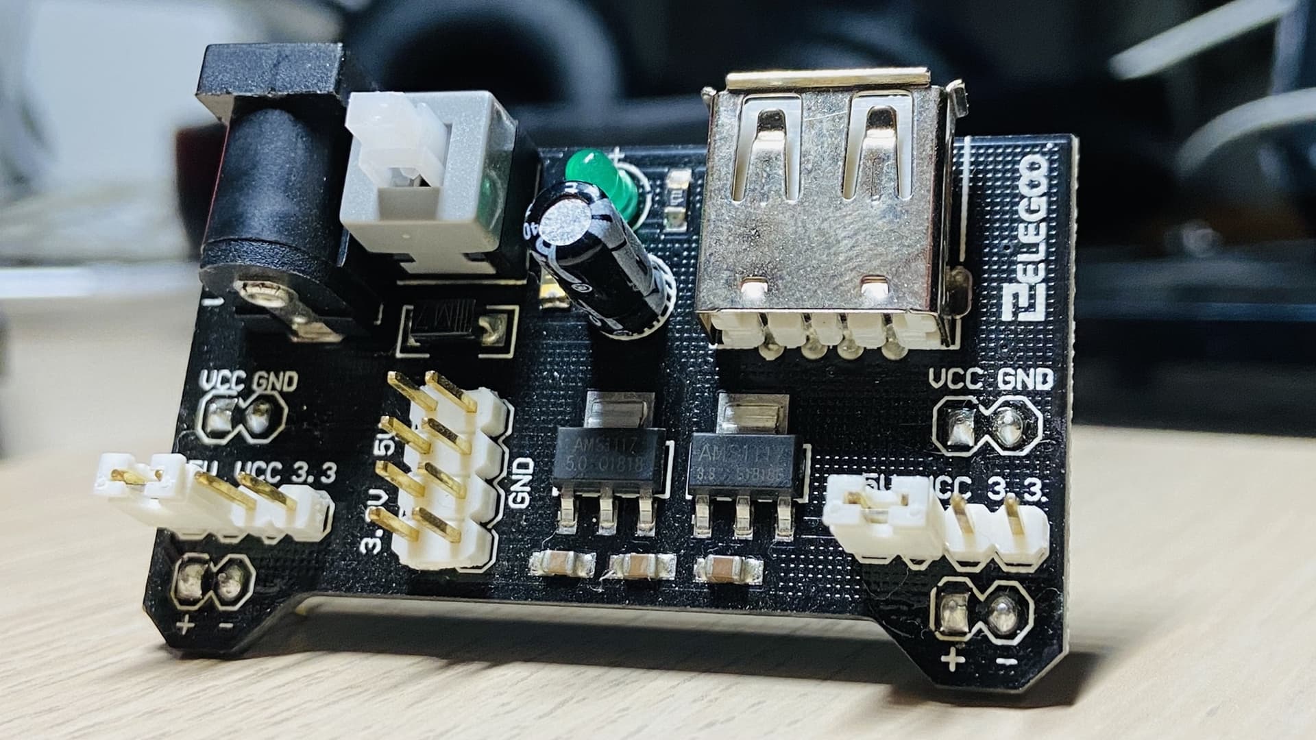
Example Hardware:

https://cookierobotics.com/042/ (NOTE: <-- I found this page super useful)

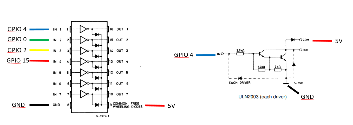
After I upload a simple program to drive the stepper using GPIO 4, 0, 2, and 15, I see the board's built-in LEDs blinking as I'd expect since those are driven by the same pins I am connecting to the ULN2003 module.

When I hook up the circuit and power it from an external 5V source, it seems to freeze up and the LEDs are on, but static, and the stepper motor will not turn.

What's odd is I only see this behavior when everything is plugged in when I turn on the power supply. If I unplug the jumpers to GPIO 4, 0, 2, and 15, turn on the power to the board, and then plug the jumpers back into GPIO 4, 0, 2, and 15, everything works fine and the stepper turns.

Because of that odd behavior, I know this isn't a code or wiring issue.

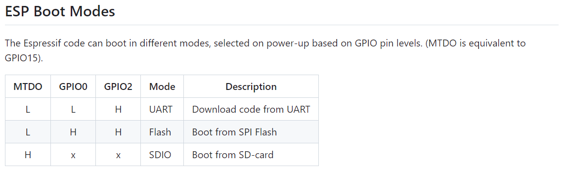
Has anyone seen and overcome this? I'm wondering if there is some special mode I'm entering by having GPIO 4, 0, 2, and 15 grounded when powering up the board?

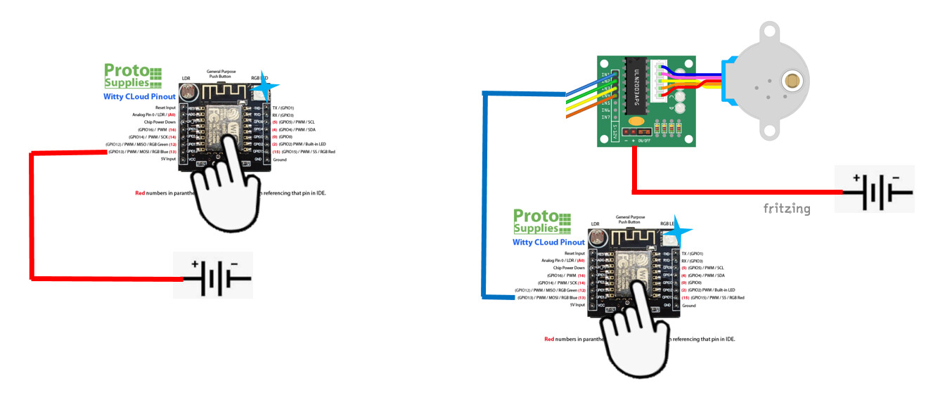
Here is an example wiring diagram:
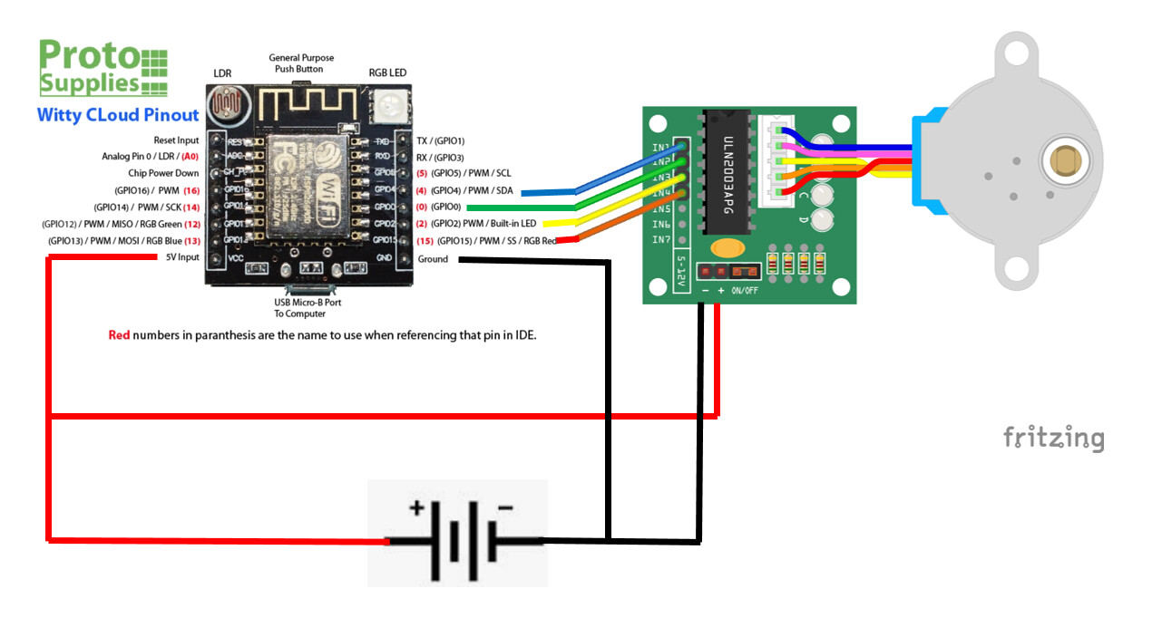
To recap:
If I power up that diagram with 5V, the LEDs (and therefore pins) have power and light up, but the motor doesn't turn.

If I unplug the wires to the GPIO pins, power up the board, and then plug in the GPIO pins, the motor turns as expected.

Yes

But in your diagram you do not show that you are grounding any pins.

I would think that connecting these pins to the ULN chip inputs would not pull them high or low, but perhaps they are.

Thanks for the response and the link.

Right, GPIO 4, 0, 2, and 15 are connected to the ULN2003 board and not directly grounded.

I've been trying to troubleshoot whether the default ULN2003 pins are LOW or HIGH and during some trial and error found that I am still seeing this behavior even when I disconnect the 5V and Ground wires going to the ULN2003 board.

I'm trying to research how the ULN2003 Darlington Arrays work. I'm not familiar with reading electronic schematics, but I found this: https://www.st.com/content/ccc/resource/technical/document/datasheet/f3/6e/c8/64/4d/b3/4e/38/CD00001244.pdf/files/CD00001244.pdf/jcr:content/translations/en.CD00001244.pdf

Is the ULN2003 driver schematic saying that the GPIO/IN and OUT are grounded when the GPIO/IN is LOW?

However, I also tried to test if maybe my breadboard or power supply is leaking power somewhere, because while I'm tinkering around I've noticed that the RGB LED lights up when I touch the chip in these configurations.

I'm wondering if this observation shows that the ULN2003 is setting the GPIO/IN to >0V in a passive way and therefore causing the boot issue. This would be contrary to my interpretation of the driver schematic where I thought the GPIO/IN are grounded, but this is my first time trying to interpret an electronic schematic with diodes and NPN transistors.

(^ EDIT: I see this same RGB LED behavior whether the 5V line is connected to the +COM or -GND input to the ULN2003 module, so I don't think this can be used to conclude whether the GPIO/IN pin is set to COM or GND by default.)

Also, in the schematics I've just shown a battery as my power supply, but I'm using an Elegoo breadboard power supply module hooked up to a 9V via the barrel jack and it is set to output 5V.

The RGB LED behavior I described above happens whether the bread board power supply is on or off, but goes away when I unplug the 9V barrel jack.

In the configuration with the ULN2003 in the open circuit, if I measure the voltage between the top of the chip and the positive rail of the breadboard, I read about 0.2 - 0.35V, this is also the voltage I read between the top of the chip and ULN2003 COM as well as the top of the chip and ULN2003 GND. The resistance between the same points is about 11.9 kOhm. Also, to be clear, the top of the ESP8266 chip is grounded to the ESP8266 Witty Cloud module's GND pin.

I'm struggling to understand the relevance of much of what you are saying.

It certainly seems that the impedance of the ULN inputs is not very high, maybe only 10~15K, and so they could be weakly pulling the ESP pins low during boot and causing it to go into an unwanted mode.

Suggest you move the ULN inputs to other ESP pins, avoiding GPIO 0, 2 & 15 which affect booting.

I'm trying to provide as many details and observations as I can, maybe they're irrelevant, but I didn't want to leave out any information I found that might have led to a solution.

I'd like to find a solution that isn't simply avoiding the problem, although I'm open to the idea that might be the ONLY solution.

I'm still struggling to understand which boot modes are being entered and what the default value of the GPIOs connected to the ULN2003 pins are.

Your source shows three boot modes:

I also found these two sources:
https://docs.espressif.com/projects/esptool/en/latest/esp8266/advanced-topics/boot-mode-selection.html#

The two new sources only describe 2 boot modes.

They all agree that the "Flash" boot mode is the normal execution mode, and the one I'd want.
This boot mode occurs when GPIOs 15, 0, and 2 are L, H, H, respectively. From what I can tell, GPIO 0 and 2 are H by default because of an internal pull-up.

I've narrowed down the cases that I enter the undesired boot mode(s) in these configurations.

The top-left one makes sense to me if we believe that the ULN2003 is causing the pin to go LOW. I'm thinking this is because if nothing plugged into GPIO 15, 0, 2 is equivalent to L, H, H, and loads us into flash boot mode. Then plugging in GPIO 0 to the ULN must be causing GPIO 15, 0, 2 to then be L, L, H, which is the UART mode. Okay, I understand that.

I'm confused by the fact that I also enter an undesired boot mode when connecting the ULN to GPIO2. If the ULN is causing pins connected to it to go LOW, then this would be setting GPIO 15, 0, 2 to be L, H, L, which I don't see in any of the boot tables I found. Do you think this is causing it to enter the SD boot mode because it doesn't fit into any of the other rows of the table?

Could I avoid this by changing any pull-up/pull-down resistors in the void setup? Or is this all happening even before it gets to that point?

It'd be ideal if I could use GPIO 0 and 2 as I intended because I am already using every (9) GPIO on the module. However, if that simply isn't possible, it appears that there are two more GPIO pins on the ESP8266 (GPIO9 and GPIO10) that are not being used/integrated into this module. Maybe I can just solder a direct connection to those instead.

Thanks for the help!

I don't know, but I guess it could be some other "undefined" boot mode. Need both 0 and 2 to be H for normal boot, that's clear.

Enabling internal pull-ups would be too late, boot is already done by the time setup() runs. You could try external pull-ups, maybe 1K to 4K7 to see what works.

Another option could be to put non-inverting buffer gates between the ESP pins and the ULN, such as 74hc245 (I think) or various other 74hcXXX. The 74hcXXX chips should have very high impedance inputs which means they won't affect the ESP boot mode.

This topic was automatically closed 180 days after the last reply. New replies are no longer allowed.