Hello, I have a project to do that is an ESR meter for both inductances and capacitors. I've been having some difficulties with this. My first taught was to make an oscillator and injecting a high frequency current (for capacitors ) in the test capacitor so that the reactance is removed. Then to introduce the resistance into a voltage divider and then measure the voltage with arduino and calculate the ESR. I tried it and I didn't get it to work.. Can someone offer me some guidance ?
There are numerous component testers in github and elsewhere that include capacitance and ESR testing. The simplest approach for you is to get one of these pre-debugged systems running. You have the choice of either stripping out the capacitance/ESR testing functionality to run on its own, or perhaps developing your own capacitance/ESR testing from first principles -- but understanding the prior implementations and design methods is going to help you a good deal.
These links are all to full-function component testers that test caps with ESR as a small part of the overall functionality. The last link provides very good description of the principles of operation for all functions, including caps/ESR.
I appreciate the help but none of those are useful for me.. I understood the principles but I can't get a working schematic...
Hi,
I'm not sure if this will help, its an analog ESR meter, but it does it at 5V level, and you may be able to transfer this basic setup to microcontroller application.
That is
Generating AC.
Detecting current across the 12R current sense resistor.
Displaying the calculated.
Can you tell us your electronics, programming, arduino, hardware experience?
Tom... ![]()
It is my first project with arduino. I looked at the link you gave me and I currently cannot get my hands on a transformer. I understood that I have to inject AC High freq signal in the capacitor and I a pretty good hardware experience so that I am able to get a schematic to work on board
Hi,
I think if you google
arduino ESR meter
Will give you some ideas, including this;
http://www.circuitbasics.com/how-to-make-an-arduino-capacitance-meter/
Tom.... ![]()
TomGeorge:
Hi,
I think if you googlearduino ESR meter
Will give you some ideas, including this;
How to Make an Arduino Capacitance Meter
Tom....
That is a capacitance meter and I did it ![]() it worked. What I need is an ESR meter for capacitors and inductances to detect if they are broken
it worked. What I need is an ESR meter for capacitors and inductances to detect if they are broken
mekowolf:
I can't get a working schematic...
In ttester_en.pdf on pages 92 and 96, exact schematics are shown for how the ESR is measured using two different approaches, along with a detailed description how the methods work. Only a handful of external resistors are needed. We know the circuit works because it is widely implemented.
gardner:
In ttester_en.pdf on pages 92 and 96, exact schematics are shown for how the ESR is measured using two different approaches, along with a detailed description how the methods work. Only a handful of external resistors are needed. We know the circuit works because it is widely implemented.
is that an arduino because i cant recognize the pins ![]()
It is the AVR pin designations for those pins of an ATMega238. One of the other links I posted was to an Arduino "wiring" port of the same code, which would mention the equivalent Arduino pin numbers.
gardner:
It is the AVR pin designations for those pins of an ATMega238. One of the other links I posted was to an Arduino "wiring" port of the same code, which would mention the equivalent Arduino pin numbers.
would that be the ardutester link?
What I need is an ESR meter for capacitors and inductances to detect if they are broken.
At the risk of asking something irrelevant and unhelpful... why bother?
I used to work in an electronics repair workshop and any component that was suspected as being fault was faulty. Even if it wasn't. The reason is simple, components are cheap (mostly) and new components are better than suspect old ones, so it a component was suspect for any reason it was replaced. No point in testing.
With apologies if that's off the point and unhelpful.
PerryBebbington:
At the risk of asking something irrelevant and unhelpful... why bother?I used to work in an electronics repair workshop and any component that was suspected as being fault was faulty. Even if it wasn't. The reason is simple, components are cheap (mostly) and new components are better than suspect old ones, so it a component was suspect for any reason it was replaced. No point in testing.
With apologies if that's off the point and unhelpful.
no worries, it is for a project at university. i really need to do this
Why not just use the Ardutester?

No worries, it is for a project at university. I really need to do this.
Good luck with your course!
Paul__B:
Why not just use the Ardutester?
I have to make it using an arduino
mekowolf:
I appreciate the help but none of those are useful for me.. I understood the principles but I can't get a working schematic...
The Ardutester article cited just above your answer gives you the working schematic.
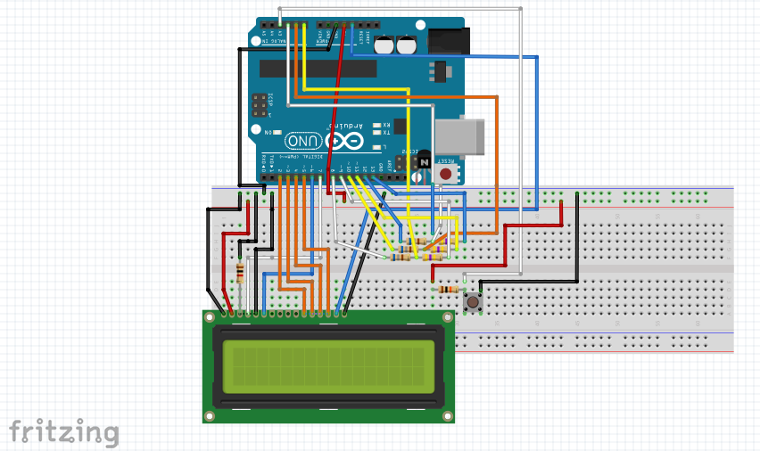
OK, it's a Fritzing diagram which is not the intellectual currency which is familiar to most of us, but it does with some difficulty, tell you how to wire it.
gardner:
In ttester_en.pdf on pages 92 and 96, exact schematics are shown for how the ESR is measured using two different approaches, along with a detailed description how the methods work. Only a handful of external resistors are needed. We know the circuit works because it is widely implemented.
This is in fact, the "Ardutester".
mekowolf:
is that an Arduino because i cant recognise the pins
You have to interpret. It should match the Fritzing diagram above.
mekowolf:
I have to make it using an Arduino
You have all the diagrams and the Ardutester code. Knock yourself out! Not sure what the whole point of this re-inventing the wheel project is.
Demonstrating in a report that you understand how the Ardutester code performs its functions does however sound like a reasonable fulfilment of the assignment rather than asserting you figured it all out for yourself.