I want to build a MIDI controller with 8 potentiometers as effect controls, 16 arcade buttons as pads, 4 pcb buttons as STOP, PLAY, REC and LOOP, 2 more pcb buttons with 2 LEDs to control the octaves and 1 switch button (ON/OFF) with 1 LED.
Im planning on buying all the components, but since im new to this im a bit confused..
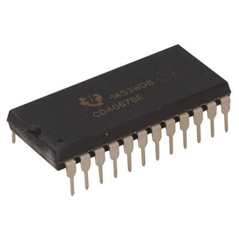
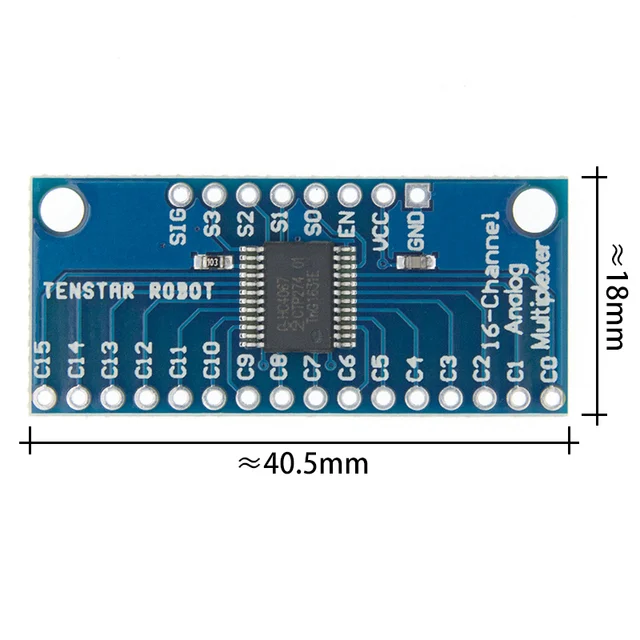
So, for what ive been seeing online im thinking in using an arduino pro micro, but if im correct it doesnt have all the inputs i need. To expand these inputs ive seen videos of people using a CD74HC4067 multiplexar (in some videos this component looked like this and in others looked like this). My two main doubts at the moment are: there is any diference between those or its just aestheticly different? Am i gonna be able to play all the 16 buttons simultaneously for example, or this multiplexar only gives me the option to play one note (button) at the time.
You don't need a multiplexer. Organise your buttons into a matrix. A 6x4 matrix will allow you up to 24 buttons using 10 pins. If it is important to be able to allow more than one button to be pressed at the same time, a small diode will need to be placed in series with each button.
Im new to eletronics and after reading your reply I got even more confused on why I dont need a multiplexar (or a shift register?) to expand the pins of the arduino while having the option to press buttons simultaneously, but I've done some research and made a draw of the layout that I want and a draw of the circuit (probably full of mistakes).
This made me question some other things like:
Do I need resistors only in the 3 LEDs or in every button, potentiometer and switch?
Do I need diodes only in the 16 arcade buttons or in every button, potentiometer and switch?
Yes, you need a series resistor for every led. You don't need series resistors for buttons or pots. You will need a diode for every button that is part of the matrix.
Thinking again about your desired circuit, perhaps you don't have enough pins after all. I was forgetting those two octave LEDs. Let me see if I can think of a way to do it without extra chips. So sorry for any confusion I caused.
But looking at your diagram, I can see that you were already very confused. I think you may be attempting to complete this project too soon. You need to do more studying and doing basic tutorials, to get all the concepts straight in your head. Only then can you start putting the pieces together to build your desired final circuit.
Lots of mistakes:-
Your record buttons are all connected to the same pin as are those two LEDs so that will never work.
Your key matrix is totally wrong, a matrix is wired in terms of columns and rows.
Each pot needs its own analogue input if you are not using a multiplexer.
As you have it you are connecting two pots for every analogue input. This means the readings will change if either pot is changed. If one pot is at the high end and the other pot at the low end you will burn out the pot.
The micro has 9 analogue inputs so plan those connected to the pot first. See the diagram. Don't bother about the pin numbers shown this just illustrates what data pins can also be used as analogue inputs.
I definitely need to study more and do tutorials. I was kinda in a hurry because I have to order the components online and they take months to arrive, so that was the reason..
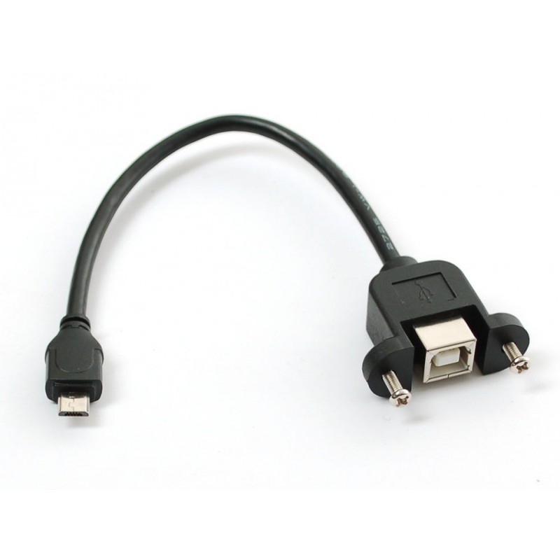
Thanks for the information and the diagram, I was not aware of that!! Yesterday after posting those drawings, I also started noticing that the power switch/LED dont makes sense where they are, they should be placed between the arduino and the computer right? I was thinking in putting an adapter like this inside the enclosure and the power switch/LED in the middle of that adapter, so that way I power off the whole controller without disconnecting from the computer.
About the Octave buttons:
No, those 2 buttons will never be pressed at the same time, for example: imagine I want to be one octave higher, I will press the "+" button and the LED is going to light up (LED shuts down when I stop pressing the button); Now I want to be 2 octaves down, I will press the "-" button 2 times and the LED light up 2 times.
ivanefl:
No, those 2 buttons will never be pressed at the same time, for example: imagine I want to be one octave higher, I will press the "+" button and the LED is going to light up (LED shuts down when I stop pressing the button); Now I want to be 2 octaves down, I will press the "-" button 2 times and the LED light up 2 times.
So all they really do is indicate that the button has been pressed? Are these leds built into the buttons?
I'm still trying to figure out a way to connect everything without an extra chip. That's why I'm asking about these things.
8 pots use 8 analog pins.
4x4 pad (with diodes) uses 8 digital pins.
Remaining pins: 1 analog, 1 digital, I think, yes?
Using a series of different value resistors, connect play/rec/stop/loop/octave+/- to the last analog pin.
1 digital pin left...
What about a apa106 led? You could use different colours to indicate different octaves: red, orange, yellow, green etc.
PaulRB:
So all they really do is indicate that the button has been pressed? Are these leds built into the buttons?
I'm still trying to figure out a way to connect everything without an extra chip. That's why I'm asking about these things.
8 pots use 8 analog pins.
4x4 pad (with diodes) uses 8 digital pins.
Remaining pins: 1 analog, 1 digital, I think, yes?
Using a series of different value resistors, connect play/rec/stop/loop/octave+/- to the last analog pin.
1 digital pin left...
What about a apa106 led? You could use different colours to indicate different octaves: red, orange, yellow, green etc.
Yes, all they do is indicating that I pressed the button and no, they dont have built in leds.
From your calculations and from what Ive seen on the arduino pro micro diagram yes we have 1 digital pin left.
About the apa106 led, that's a great idea!! I didn't thought about it, but yeah It can be only one led there, even if its only one color theres no problem, since its just for indicating that one of the buttons has been pressed. Although, as u said putting an apa106 led would be a great addition to indicating different octaves.
Great! And you can chain a few other apa106 leds to the first one, if you have a use for them, with no more Arduino pins needed.
My biggest fear is that one day you want to extend the project but there are no pins left, no chance to add another chip. If this is a concern for you also, I recommend this: save the i2c pins (SCL+SDA). These pins are incredibly useful, alowing you to add many extra chips, giving extra digital pins or analog pins, all connected to those same 2 arduino pins. Much more flexible than a multiplexer chip. For example a pcf8574 chip could be used to read the 4x4 pad, and in effect it uses no arduino pins, because SCL+SDA are still available to connect other pcf8574 chips or other chips.
PaulRB:
Great! And you can chain a few other apa106 leds to the first one, if you have a use for them, with no more Arduino pins needed.
My biggest fear is that one day you want to extend the project but there are no pins left, no chance to add another chip. If this is a concern for you also, I recommend this: save the i2c pins (SCL+SDA). These pins are incredibly useful, alowing you to add many extra chips, giving extra digital pins or analog pins, all connected to those same 2 arduino pins. Much more flexible than a multiplexer chip. For example a pcf8574 chip could be used to read the 4x4 pad, and in effect it uses no arduino pins, because SCL+SDA are still available to connect other pcf8574 chips or other chips.
Thats excellent!! Probably I will not extend or add more things to this controller in the future, but to see if I understood correctly... If that was a concern to save those 2 pins (i2c), u recommend use a pcf8574 breakout board to read the 4x4 pad because instead of using 8 pins, I could simple use 4 pins for the pcf8574 and save the other ones which includes i2c pins, right? (Just found out what a breakout board is)
I have 3 more questions that I would be really appreciated if u could answer them.
1- Do I also need a resistor for the apa106 led?
2- What kind of diodes do I need for the pads buttons?
3- The problem of using a multiplexar or a shift register is that they dont give me the ability to play multiple buttons at the same time?
I could simple use 4 pins for the pcf8574 and save the other ones which includes i2c pins, right?
No not quite. A pcf8574 chip requires two pins to drive it. Those same two pins can be used to connect other devices to the Arduino. In theory you can directly drive 128 devices from these two pins.
1- Do I also need a resistor for the apa106 led?
Yes a small one say 330R in seriese with the data lines. Not to limit the current like a normal LED's resistor, but to prevent reflections on the data line.
2- What kind of diodes do I need for the pads buttons?
Signal diodes, typically a 1N4148 is a popular choice.
3- The problem of using a multiplexar or a shift register is that they dont give me the ability to play multiple buttons at the same time?
Well done I wondered how long it would take someone to point this out. It is totally irrelevant to the OPs problems and only adds needless complications to confuse a beginner. But well done, you did it.


