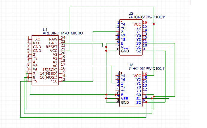
johnwasser:
Sounds like there is a mistake in some part of the sketch that you did not show. If you would like assistance in finding the mistake, please post the entire sketch.
I have days trying to make it works, so yes i want to find the mistake. Thanks for your help.
Here is all code that i am using. I have comment the section when it read direct analog pins in Arduino to not get data from there.
Source internet.
//Total num of MIDI controls
#define NUM_CONROLS 15
//Num of channels to read directly through analog pins
#define ANALOG_NUM_CHANNELS 0
//Num of channels read through 74HC4051 mux chip
#define MUX_NUM_CHANNELS 15
//Mux output to Arduino analog pin
#define MUX_COM A10
#define MUX_COM2 A0
//Mux address select digital pins
#define MUX_ADDRESS_SEL_0 7
#define MUX_ADDRESS_SEL_1 8
#define MUX_ADDRESS_SEL_2 9
//Debug baud rate
#define SERIAL_RATE 9600
//MIDI channel to use
#define MIDI_CHANNEL 0
//CC slots 14-31 are recognized as assignable controls by MIDI standard
#define MIDI_CC_START 14
//maps to map log taper slider pots to linear readings
int sliderFromMap[] = {0, 1023};
int sliderToMap[] = {0, 127};
byte sliderFromMapSize;
byte sliderToMapSize;
//maps to map log taper rotary pots to linear readings
int knobFromMap[] = {0, 55, 130, 516, 1023};
int knobToMap[] = {0, 127};
byte knobFromMapSize;
byte knobToMapSize;
//Holds current MIDI control values
int ccValue[NUM_CONROLS];
//Stores pin numbers of analog channels
byte analogChannelPin[ANALOG_NUM_CHANNELS];
void setup()
{
Serial.begin(SERIAL_RATE);
pinMode(MUX_ADDRESS_SEL_0, OUTPUT);
pinMode(MUX_ADDRESS_SEL_1, OUTPUT);
pinMode(MUX_ADDRESS_SEL_2, OUTPUT);
sliderFromMapSize = sizeof(sliderFromMap) / sizeof(int);
sliderToMapSize = sizeof(sliderToMap) / sizeof(int);
knobFromMapSize = sizeof(knobFromMap) / sizeof(int);
knobToMapSize = sizeof(knobToMap) / sizeof(int);
/* analogChannelPin[0] = A0;
analogChannelPin[1] = A1;
analogChannelPin[2] = A2;
analogChannelPin[3] = A3;*/
}
void loop()
{
//Loop through all mux channels
  for (byte muxChannel = 0; muxChannel < MUX_NUM_CHANNELS; ++muxChannel)
  {
    int midiValue = multiMap(readMuxChannel(muxChannel), sliderFromMap, sliderFromMapSize, sliderToMap, sliderToMapSize);

    if (ccValue[muxChannel] != midiValue)
    {
      ccValue[muxChannel] = midiValue;
      midiControlChange(MIDI_CHANNEL, MIDI_CC_START + muxChannel, midiValue);
    }
  }
/*
//Loop through all analog channels
for (byte analogChannel = 0; analogChannel < ANALOG_NUM_CHANNELS; ++analogChannel)
{
int analogValue = analogRead(analogChannelPin[analogChannel]);
int midiValue = 0;
if (analogChannel == 0)
{
//read single remaining slider
midiValue = multiMap(analogValue, sliderFromMap, sliderFromMapSize, sliderToMap, sliderToMapSize);
}
else
{
//the rest are rotary pots
midiValue = multiMap(analogValue, knobFromMap, knobFromMapSize, knobToMap, knobToMapSize);
}
if (ccValue[MUX_NUM_CHANNELS + analogChannel] != midiValue)
{
ccValue[MUX_NUM_CHANNELS + analogChannel] = midiValue;
midiControlChange(MIDI_CHANNEL, MIDI_CC_START + MUX_NUM_CHANNELS + analogChannel, midiValue);
}
}*/
}
//Reads analog value of mux chips at selected channel
int readMuxChannel(byte channel)
{
  // Select which mux: 0 (on A0) or 1 (on A10)
  bool whichPin = (channel >> 3) & 1;

  //Select mux channel: 0:7
  digitalWrite(MUX_ADDRESS_SEL_0, channel & 1);
  digitalWrite(MUX_ADDRESS_SEL_1, (channel >> 1) & 1);
  digitalWrite(MUX_ADDRESS_SEL_2, (channel >> 2) & 1);

  //Read mux output
  return analogRead(whichPin ? A0 : A10);  // 0 through 7 on A0, 8 through 15 on A10.
}
//Linear interpolates a value in fromMap to toMap
int multiMap(int value, int fromMap[], int fromMapSize, int toMap[], int toMapSize)
{
//Boundary cases
if (value <= fromMap[0]) return toMap[0];
if (value >= fromMap[fromMapSize - 1]) return toMap[toMapSize - 1];
//Find the fromMap interval that value lies in
byte fromInterval = 0;
while (value > fromMap[fromInterval + 1])
fromInterval++;
//Find the percentage of the interval that value lies in
float fromIntervalPercentage = (float)(value - fromMap[fromInterval]) / (fromMap[fromInterval + 1] - fromMap[fromInterval]);
//Map it to the toMap interval and percentage of that interval
float toIntervalPercentage = ((fromInterval + fromIntervalPercentage) / (fromMapSize - 1)) * (toMapSize - 1);
byte toInterval = (byte)toIntervalPercentage;
toIntervalPercentage = toIntervalPercentage - toInterval;
//Linear interpolate
return toMap[toInterval] + toIntervalPercentage * (toMap[toInterval + 1] - toMap[toInterval]);
}
//Sends MIDI CC signal
void midiControlChange(byte channel, byte ccNum, byte value)
{
//Send a MIDI control change event through USB
MIDIEvent event = {0x0B, 0xB0 | channel, ccNum, value};
MIDIUSB.write(event);
MIDIUSB.flush();
}
