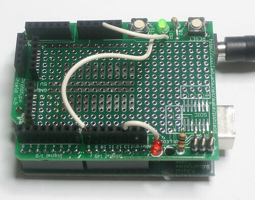
How can I use the extra button (not the reset button) and LEDs on this expansion board (see image)? I have searched for some example code but I couldn't find anything.
You don't need to look hard the arduino has examples for how to use buttons and leds. Start with the basics.
Just change the code to use the pins your led is on and your buttons. You can then add more as you see how this works.
/*
  Button

 Turns on and off a light emitting diode(LED) connected to digital
 pin 13, when pressing a pushbutton attached to pin 2.


 The circuit:
 * LED attached from pin 13 to ground
 * pushbutton attached to pin 2 from +5V
 * 10K resistor attached to pin 2 from ground

 * Note: on most Arduinos there is already an LED on the board
 attached to pin 13.


 created 2005
 by DojoDave <http://www.0j0.org>
 modified 30 Aug 2011
 by Tom Igoe

 This example code is in the public domain.

 http://www.arduino.cc/en/Tutorial/Button
 */

// constants won't change. They're used here to
// set pin numbers:
const int buttonPin = 2;     // the number of the pushbutton pin
const int ledPin =  13;      // the number of the LED pin

// variables will change:
int buttonState = 0;         // variable for reading the pushbutton status

void setup() {
  // initialize the LED pin as an output:
  pinMode(ledPin, OUTPUT);
  // initialize the pushbutton pin as an input:
  pinMode(buttonPin, INPUT);
}

void loop() {
  // read the state of the pushbutton value:
  buttonState = digitalRead(buttonPin);

  // check if the pushbutton is pressed.
  // if it is, the buttonState is HIGH:
  if (buttonState == HIGH) {
    // turn LED on:
    digitalWrite(ledPin, HIGH);
  }
  else {
    // turn LED off:
    digitalWrite(ledPin, LOW);
  }
}
@Bups76
BTW
I took three single female headers and soldered them in the holes so wires can be plugged in just as you do on the proto board
@LarryD, thanks a lot. You made me understand how to use the LEDs and switch.
There a little more learning I think you better know that the switch needs a resistor or use built in pull ups because if you hooked it to a input It's not going to read right. Or if you mistakenly hook it to 5 volts it's will be a short when pressed.
On a double sided board like that, you can follow the traces.
aarg:
On a double sided board like that, you can follow the traces.
How can I do this? "Follow the traces"
It's not that easy some are small go under writing and come out somewhere else you have to learn how to see where the go and how to use a dvm meter to make sure your right.
You'd be better off learning to read and look for the documentation and the schematic first so you see how it looks and then try to find the traces. https://learn.adafruit.com/downloads/pdf/adafruit-proto-shield-arduino.pdf
Hi,
I have recently had to do a quick prototype to low production run job, I needed about 5 test points to check on each board and I found these headers, cut into single sockets were ideal.
The machined socket holds the test probe, (DuPont and generic jumpers we use on protoboard) and has a low profile.
They are used to make on board IC sockets.
Tom.... ![]()


