I am deigning a small power metering device that would measure power consumption in house appliances and connect via WiFi (esp8266) to Home Assistant.
The project is based on the BL2525 power measurement chip and it also involves a transformerless supply of 3.3V from mains (yes, I know its dangerous!)
The datasheet of the BP2525_EN.pdf (908.0 KB)
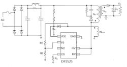
includes a recommended application setup, however while searching the net for similar applications I come across the following configuration with two capacitors and an inductor after the rectification stage:
This setup appears to be used a lot in similar designs.
Can anyone explain the purpose of this block?
The inductor and capacitors will filter out high freq. noise from AC.
High freq noise is present from motors with brushes (drilling machines) but also from switching power supplies. And from solar feed and so on...
Some communication systems delibrately put high freq signals on mains as means of 'wireless' communication.
Also the 0.6V over the diodes will cause high freq noise...
The capacitors and inductor are to keep noise generated by the BP2525 from entering onto the AC mains line, NOT the other way around.
You may need those components in order to pass EMC testing.
For a hobby project, may not be needed