trsuthbu888:
if you recall my very first questions, some time ago - about wiring signals for 5-7 meters away from the Arduino
Ah well, there is the trick, isn't it? Basically "Cross posting" where the basic description appears in one post, then a new aspect appears in a separate question relying on information in the other posting.
Frankly I do not recall your other questions; I imagine I may well have answered them, but then I answer a lot of things by the look of my post count.  I expect to give the same sort of answers, and keep a file of "stock" answers to facilitate this, but recalling every discussion in detail is a bit much to ask.
And you did not provide a link; you only have 27 posts noted so far so I could track it down but - should I really have to?
trsuthbu888:
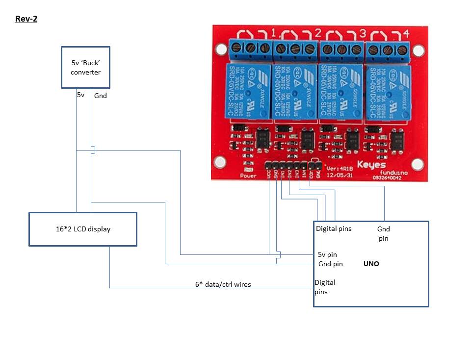
so I have the main power supply (24v) at Location-1 (it is the same location with the relays - activating the needed appliances). From that location, I have 5-7 meters wires to Location-2 , where the Arduino and LCD will be (plus some diodes and press-switches).
OK, this sounds reasonable. This means you absolutely do want to use the isolation feature of the relay board and using two separate buck converters sounds quite necessary for the following reason.
trsuthbu888:
My thinking is:
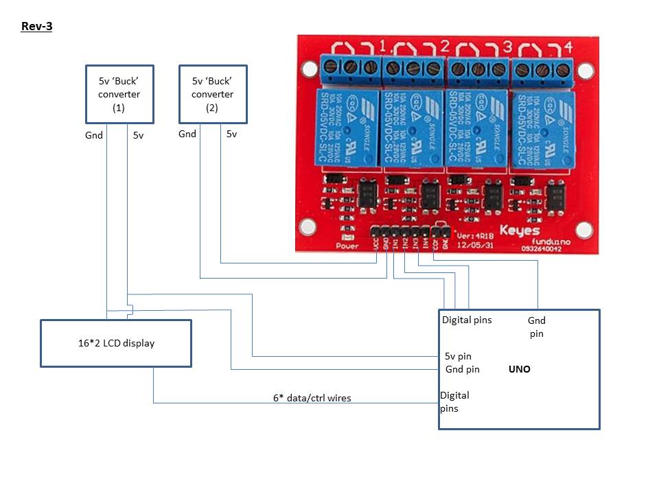
- To put 1 buck-converter at Location-1 - to supply the relay module alone.
- To wire the main power supply (24v) from Location-1 to Location-2, and produce 5v locally with the second buck.
Like that - to avoid wiring back 5v supply from Location-2 to Location-1. It seems logical, taking into account all the surge-coupling-etc issues.
Well, you will be wiring the 5 V "back" from your second (MCU) location to the first (relays)- at least the ground side - but it will be isolated and control signals only. That is the point about the separate ground grouped with the "IN" signals to the relays.
I believe you can use "Cat 5" for this purpose. One pair to take 24 V from the source forward to your Arduino with the buck regulator and three pairs to take the control signals back to the relays. Since the relays are isolated and the regulators should suppress impulses in the power wiring, there is no common ground wire to couple between power, relays and control signals.
trsuthbu888:
Following this design - would you recommend on other safety measures (more capacitors at other locations etc) to make the design 100% reliable?
[/quote]
Yes, extra capacitance at the power connections of the relay board is always advised as this is where the "kickback" of relay coil switching is felt. And additional reservoir capacitors across the input of each buck regulator would be good.
Do not connect the Arduino equipment to a local ground, especially if the 24 V supply itself grounds the negative (we would always assume it does not ground the positive! ).