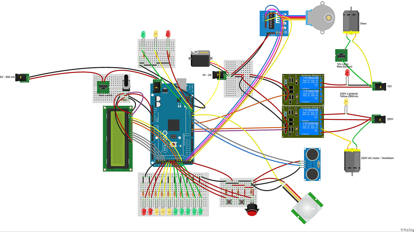
Can I install an external 5V power supply like on the picture ?
Because I've read that the board can't deliver more than 500 mA so I want to install a 2A transfo. (because I got a servo, 3 relays, 1 LCD display, 1 stepper... and I think it's a lot)
Can I connect the power of the board like this ?
Thanks for your answers !
I would suggest you power all the motors/servos/relays from the external 5V supply, and
use the Arduino 5V for just the LCD. Don't mix inductive loads with delicate circuitry.
Common the grounds.
You cannot power an Arduino by putting 5V into Vin. 7V or more is needed for that.
I have to put ALL the grounds on the same point ? (of my external supply for example ?)
So, I have to connect the Arduino (and so the LCD) to another 5v supply (in the USB for example) and NOT with the external 5V supply ? I can't use the 12V to VIN because there is a motor on it, isn't it ?
OK OK. So it's not a problem if I connect the arduino on the 12v supply and that there is a motor yet on the 12 V ? (as said on the previous advice of MarkT)
I've got lots of old 12 V and 5v supply, it isn't a problem to put one more supply for the Arduino. What is the best ?
And for the grounds, I put all of them on same point ? (for exemple, the ground of the 10 leds on my external 5v supply ?
You can NOT run the Mega from a 12volt supply with 13 LEDs (with 220ohm CC resistors) and an LCD with LED backlight. That, including the Mega, would draw ~250mA.
With a (12-5) = 7volt drop, the onboard regulator would have to dissipate 7volt * 0.25A = 1.75watt.
Enough heat for a thermal shutdown.
12volt on the DC socket is better (0.7volt reverse protection diode drop), but that still would be 1.57watt.
Are 220ohm CL resistors needed? 470ohm or 1k could be bright enough.
A 5volt phone charger on the USB socket bypasses the onboard regulator.
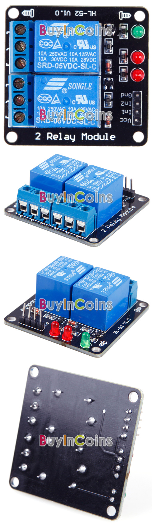
That relay link is for many relays. Which one are you using.
Leo..
Oops, that's the "2 Channel Relay (W/ LED Indicator)".
Everything is possible, I'm just looking for THE solution. I have many power supply at home, if you say that I've to put a new power supply only for the Arduino, I will do it. I don't want to burn my MEGA. I can put bigger resistors for the LED indeed. So it's a better idea to reduce power as you said (220 ohms is the minimum I have calculated but it's true that a can put bigger ones)
My first idea was :
To put a 5V phone charger on the USB SOCKET of the Arduino and NOT the 12V on the Vin (If I do that, have I to put bigger resistors on LED or not ?)
5volt on the USB socket (or the 5volt pin) is ok. 5volt on the DC socket is not.
The DC socket needs 7volt minimum for the onboard 5volt regulator to work.
Servo ground has to be connected to Arduino.
The linked relay board doesn't seem to have opto isolation, the Fritzing picture has.
No optos means relay board ground and Arduino ground have to be shared.
Optos means VCC (not ground) has to be shared, with JD-VCC jumper removed.
Post a real picture of your relay boards to be sure.
Leo..
tryptophane:
Oops, that's the "2 Channel Relay (W/ LED Indicator)".
Everything is possible, I'm just looking for THE solution. I have many power supply at home, if you say that I've to put a new power supply only for the Arduino, I will do it. I don't want to burn my MEGA. I can put bigger resistors for the LED indeed. So it's a better idea to reduce power as you said (220 ohms is the minimum I have calculated but it's true that a can put bigger ones)
My first idea was :
To put a 5V phone charger on the USB SOCKET of the Arduino and NOT the 12V on the Vin (If I do that, have I to put bigger resistors on LED or not ?)
An external 5v for all the motors, relays,...
An external 12V for all 12v gears.
I think it's the easier way. What do you think ?
Have a nice day !
It sounds reasonable. It would be nice to generate the motor 5V from the motor 12V, as
that would reduce the number of power supplies, but that's probably fairly high current
and beyond the ability of the cheap LM2596's on eBay.