So what's the difference between your breadboard set-up and your project set-up?
That is your answer.
-
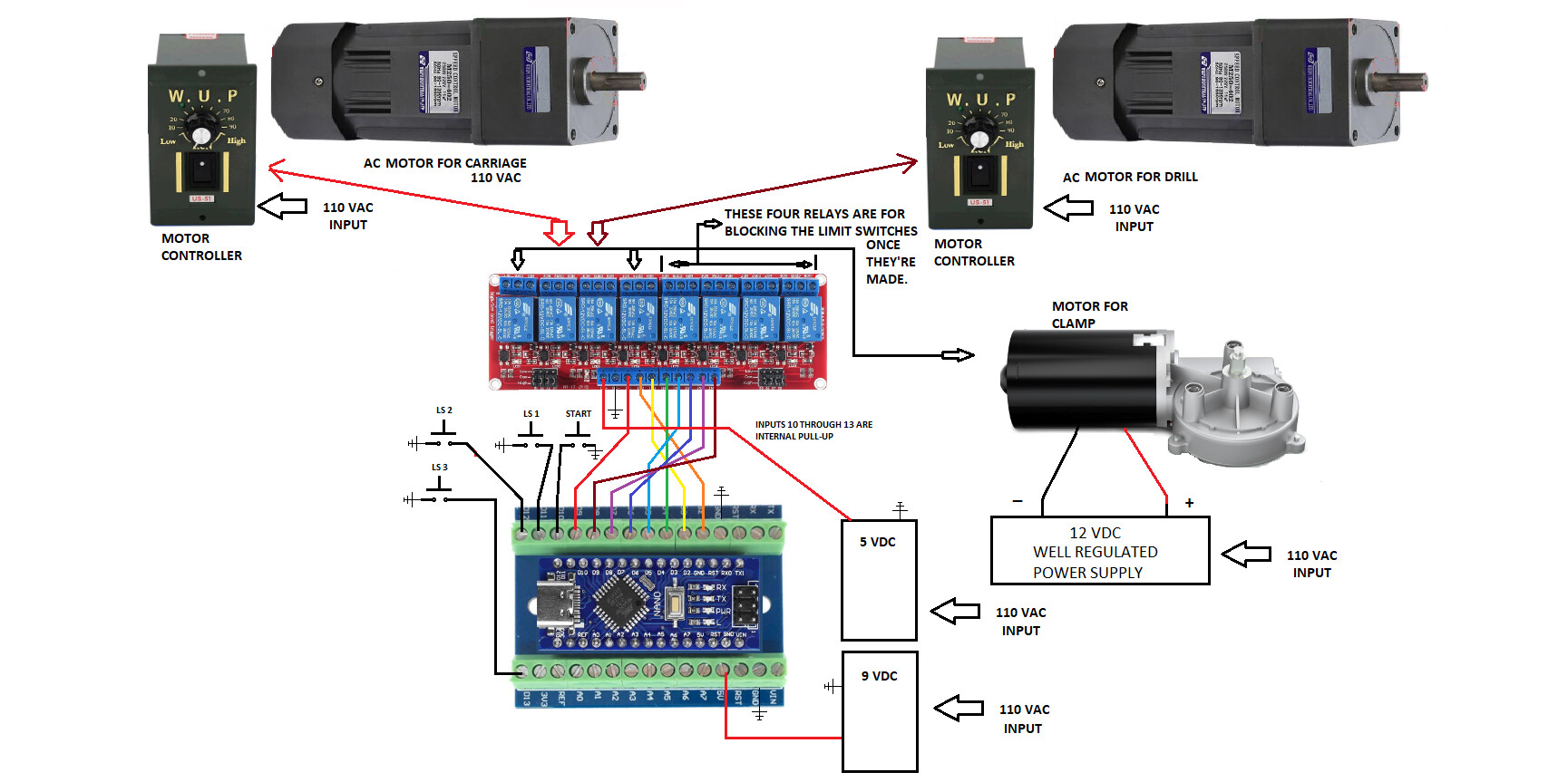
The clamp is actually driven by a DC motor also controlled by a relay,
-
The relay board is a 5 volt board and is actually powered by the 5 volts output from the nano.
- My switch wiring is roughly 15 to 18 in long some shorter, however none of them run in parallel with any power lines.
- As soon as I apply power to the nano it goes into action and starts working its way through the code without the buttons/switches being pushed.
The difference between the breadboard and where I’ve installed it is mainly the AC current,
whereas the breadboard has no AC anywhere around it, this is what led me to believe it may be RF interference coming from the AC.
Thank you, that is very helpful, I will apply those changes and check it out.
It's not RF but 50/60Hz electromagnetic interference. Even without the motors connect the wires can still radiate interference.
Is the Nano powered the same way in both cases?
But is it disconnected at the moment from relay like the AC motor?
Not the best approach for 8 relay coils that draw ~500mA all together. Especially if you power nano from VIN?
Hi, @gmcappy53
Can you please post some images of your project?
So we can see your component layout.
Tom.... 


- Powering your relay module from the Arduino 5V pin will cause problems, use an external 5V power supply.

I did try powering through the micro USB port, however I still had the same problem.
I also tried an independent 5 volt power supply just for the relays and still had the same problem.
I don't see any AC.
Where is this AC you mentioned?
 pinMode(5, OUTPUT);
 pinMode(10, INPUT);
 pinMode(7, OUTPUT);
 pinMode(1, OUTPUT);
 pinMode(11, INPUT);
 pinMode(6, OUTPUT);
 pinMode(2, OUTPUT);
 pinMode(12, INPUT);
 pinMode(8, OUTPUT);
 pinMode(3, OUTPUT);
 pinMode(13, INPUT);
 pinMode(4, OUTPUT);
-
Your inputs should have pull up resistors turned on.
example:pinMode(10, INPUT_PULLUP); -
You cannot power the relays from the NANO’s 5v pin.
-
The NANO Vin pin should be lower, from 7V to 9V.
-
If the relays are set for LOW active, turn off the NANO’s outputs to the relay module before making them OUTPUTs.
Example:
digitalWrite(5, HIGH);
pinMode(5, OUTPUT);
- Show us the updated sketch.
This is my revised sketch, please check it out and see if I understood you correctly thank you so much.

// C++ code
//
int buttonState = 0;

void setup() {
  pinMode(5, OUTPUT);
  pinMode(10, INPUT);
  pinMode(7, OUTPUT);
  pinMode(1, OUTPUT);
  pinMode(11, INPUT);
  pinMode(2, OUTPUT);
  pinMode(12, INPUT);
  pinMode(6, OUTPUT);
  pinMode(3, OUTPUT);
  pinMode(13, INPUT);
  pinMode(4, OUTPUT);

  digitalWrite(5, HIGH);
  pinMode(5, OUTPUT);
  // BLOCKS LS. 3
}

void loop() {
  // START BUTTON
  buttonStatetate = digitalRead(10);
  if (buttonState == HIGH) {
    digitalWrite(7, HIGH);
    pinMode(7, OUTPUT);
    // BLOCKS START BUTTON
    digitalWrite(9, HIGH);
    pinMode(9, OUTPUT);
    // CLAMP CLOSING
  }
  // LS.1, CLAMP CLOSED
  buttonState = digitalRead(11);
  if (buttonState == HIGH) {
    digitalWrite(9, LOW);
    // CUTS POWER TO CLAMP
    delay(1000);  // Wait for 1000 millisecond(s)
    digitalWrite(2, HIGH);
    pinMode(2, OUTPUT);
    // POWERS MOTORS
    delay(6000);  // Wait for 6000 millisecond(s)
    // LS. 3 IS NO LONGER BLOCKED
    digitalWrite(5, LOW);
  }
  // LS. 2, MOTORS FORWARD
  buttonState = digitalRead(12);
  if (buttonState == HIGH) {
    delay(25);  // Wait for 25 millisecond(s)
    digitalWrite(6, HIGH);
    pinMode(6, OUTPUT);
    // BLOCKS LS. 2
    digitalWrite(2, LOW);
    // TURNS OFF MOTORS
    delay(2000);  // Wait for 2000 millisecond(s)
    digitalWrite(3, HIGH);
    pinMode(3, OUTPUT);
    // PUTS MOTORS IN REVERSE READINESS
    delay(1000);  // Wait for 1000 millisecond(s)
    digitalWrite(2, HIGH);
    pinMode(2, OUTPUT);
    // STARTS MOTORS IN REVERSE
    delay(3000);  // Wait for 3000 millisecond(s)
    digitalWrite(6, LOW);
    // LS.2 IS NO LONGER BLOCKED
  }
  // LS. 3
  buttonState = digitalRead(13);
  if (buttonState == HIGH) {
    delay(500);  // Wait for 500 millisecond(s)
    digitalWrite(5, HIGH);
    pinMode(5, OUTPUT);
    // BLOCKS LS. 3
    digitalWrite(2, LOW);
    // CUTS POWER TO MOTORS
    delay(1000);  // Wait for 1000 millisecond(s)
    digitalWrite(3, LOW);
    // PUTS MOTORS IN FORWARD READINESS
    delay(1000);  // Wait for 1000 millisecond(s)
    digitalWrite(4, HIGH);
    pinMode(4, OUTPUT);
    // STARTS CLAMP OPEN
    delay(15000);  // Wait for 15000 millisecond(s)
    digitalWrite(4, LOW);
    digitalWrite(7, LOW);
  }
}
I realized I forgot to show you my input changes so here they are.
void setup() {
  pinMode(5, OUTPUT);
  pinMode(10, INPUT_PULLUP);
  pinMode(7, OUTPUT);
  pinMode(1, OUTPUT);
  pinMode(11, INPUT_PULLUP);
  pinMode(2, OUTPUT);
  pinMode(12, INPUT_PULLUP);
  pinMode(6, OUTPUT);
  pinMode(3, OUTPUT);
  pinMode(13, INPUT_PULLUP);
  pinMode(4, OUTPUT);
I don't see this this AC anywhere that is causing the problem
void setup() {
  pinMode(5, OUTPUT);
  pinMode(10, INPUT);
  pinMode(7, OUTPUT);
  pinMode(1, OUTPUT);
  pinMode(11, INPUT);
  pinMode(2, OUTPUT);
  pinMode(12, INPUT);
  pinMode(6, OUTPUT);
  pinMode(3, OUTPUT);
  pinMode(13, INPUT);
  pinMode(4, OUTPUT);

  digitalWrite(5, HIGH);
  pinMode(5, OUTPUT);
  // BLOCKS LS. 3
}
-
You are not following directions, as a result, I will be leaving after this post.
-
Your outputs above do not agree with the schematic.
- This is how to treat your outputs if they are set to LOW active.
void setup() {
  //Ouputs
  digitalWrite(1, HIGH);
  pinMode(1, OUTPUT);   // <———<<<< don’t use pin 1

  digitalWrite(2, HIGH);
  pinMode(2, OUTPUT);

  digitalWrite(3, HIGH);
  pinMode(3, OUTPUT);

  digitalWrite(4, HIGH);
  pinMode(4, OUTPUT);

  digitalWrite(5, HIGH);
  pinMode(5, OUTPUT);

  digitalWrite(6, HIGH);
  pinMode(6, OUTPUT);

  digitalWrite(7, HIGH);
  pinMode(7, OUTPUT);

  //Inputs
  pinMode(10, INPUT_PULLUP);
  pinMode(11, INPUT_PULLUP);
  pinMode(12, INPUT_PULLUP);
  pinMode(13, INPUT_PULLUP);
// C++ code
//
int buttonState = 0;

void setup() {
  pinMode(5, OUTPUT);
  pinMode(10, INPUT_PULLUP);
  pinMode(7, OUTPUT);
  pinMode(9, OUTPUT);
  pinMode(11, INPUT_PULLUP);
  pinMode(2, OUTPUT);
  pinMode(12, INPUT_PULLUP);
  pinMode(6, OUTPUT);
  pinMode(3, OUTPUT);
  pinMode(13, INPUT_PULLUP);
  pinMode(4, OUTPUT);

  digitalWrite(5, HIGH);
  pinMode(5, OUTPUT);
  // BLOCKS LS. 3
}
Well as I pointed out (post #25) that is your problem but you have not done anything yet
My schematic is no longer relevant, as I am making changes according to your suggestions, please be patient with me as I am really trying to learn this.
Allow me to explain myself a little more, I’m 60 years old and for more than 20 of those years I worked as an electrician, so I understand electricity, I also understand electronics, however microcontrollers are a whole new thing to me, I can clearly see the value in them and I really want to work with them and use them, I have successfully completed some small simple projects with them, however this is the biggest project I’ve worked on involving microcontrollers, and I’ve run into a problem I have not run into before.
I am very grateful for your time and willingness to help me work through this, I am currently working two jobs and trying to work on this project in between so it’s taking me a little bit of time to work through this, I don’t have the pictures of the project at this point because in the process of trying to find out why it wasn’t working I’ve basically ripped it apart, So I’m trying to put things back together the right way so I can get some photos, until then I’m having to put some things together to try to show you what I’ve got, so the following is what I’m working with and trying to implement the suggestions you’ve all made.
Again I am extremely grateful for all of your help thank you so much.
This is a drawing of how things look now, it includes the motors that I will be using;