Fan-speed-control: Switch between 3 relays with only one button

Hi everyone!!

I´m new here and relatively new to Arduino and everything having to do with programming.

I can´t find a solution to switch between 3 relays by only pressing one button.
I have a 4 Relay Module connected to a ESP8266. The 1st relay will be used to switch the fan on & off
(I´m fine with that - that´s pretty easy) but... the second button should alternate between relay 2 - 3 and 4 in a loop.

2nd relay 1st speed
3rd relay 2nd speed
4th relay 3rd speed

Fan Speed 1 - Press button - Fan Speed 2 - Press button - Fan Speed 3 - Press button - repeat.

I have downloaded several libraries and tried to work my way trough, read a couple of articles and searched the web, but I somehow can´t figure it out. Can anyone help?

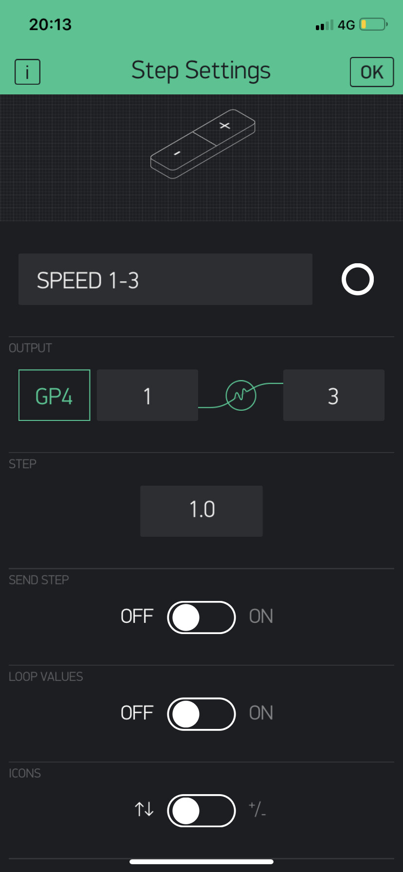
Project.: I´m working on a wireless Fan-speed controller controlled by Blynk-App

I have already designed a remote control via the Blynk App for my little weatherstation I´ve build.
Its monitoring Temp, Humidity and Lx-intensity. giving me output on a little 128x64 Oled-screen and transmitting data to the phone.
That´s basically everything I´ve done so far ^^

Thank you everyone! :slight_smile:

Please post your code so far as is, or your best attempt to solve this. I first started posting some pseudocode to give you a code outline, but I stopped because I thought you might be entirely confused with that. So, let's start with the code you have so far, and build on that.

You want code or advice? Break the problem down, you have several parts that are easy to do, then just connect them.

  1. read a button switch
  2. increment a counter
  3. use the counter to select one relay
  4. operate the relay

Really, all of these things are easy to do by themselves and if you work on them independently, you will probably find it not so hard to put them together into a working sketch.

That was quick...

@Perehama my sketch is a total playground. I´ll better keep on trying to get somehow close before sharing.

@aarg: Many thx for the quick reply!
If with these steps i´ll get closer to my goal I at least know what to look for as I´m totally lost at this point.
All this is such a new world for me..

I´ll keep on trying and let you guys see what I´ve come up with.

PD: Didn´t ask for a code as I want to accomplish it my self :slight_smile:

it doesn't matter if your code does look like a "playground" (usually playgrounds look pretty nice)

If you post your code as it is you can even receive advice on how to improve your code to look better.

best regards Stefan

aarg:

  1. read a button switch
  2. increment a counter
  3. use the counter to select one relay
  4. operate the relay
  1. probably the hardest part... because of a phenomenon called bounce, that is when one force overtakes another, the tendency for the state to bounce between forces before resting on a final state. This means when you push the button, you might change speeds a few times per button press if you don't have the input properly debounced. external to the MCU this is usually a capacitor, a r/c circuit, a diode/cap circuit etc. If you are new to this and don't know what is best, a 100nF capacitor between the input and ground should be enough external to "square off" the input. In code, you will also want to lock-out the input for a few milliseconds to prevent multiple counts on the same press. The button will bounce on the push and on the release... a push-button has 2 forces, mechanical (i.e. your finger against a spring) and electrical... when you push the button, you want to pull the input pin HIGH or LOW, but when you release it, you will want something to pull it opposite. This is usually a resister of some light value (10k) tied to the opposite pole, so if your finger takes it LOW the resistor will take it HIGH when you let go.
  2. fairly easy
if (counter >= 2) counter = 0;// the next part will be 0-indexed, meaning the first position is 0
else counter++;// so we will count from 0-2 instead of 1-3

3 & 4) in addition to closing the right relay, you have to open the other two, or at the very least, the previous relay this can be done a number of ways, calling one of 3 functions, a switch case, iterating over 1 dimension of a 2-dimensional array etc.
If you had everything else done, we could focus on this....

Since yesterday I´m 15 hours in and did not advance one bit. so.. here I am again.

As the ESP8266 only works with 3.3V and my relays need 5V I switched the setup to LEDs. (already ordered a XL6009 DC-DC Booster and an ESP32 - as i´ll need more Outputs)

Just read the info-box of Blynk regarding my so thought "pushButton" and its not. its a step control.
It says that its like 2 buttons assigned to 1 pin. One button increments the value by desired step and another one decrements it. I assume that changes everything.

PD: I´m reading certain texts again and again and again and don´t understand anything.
Not sure if its because of the language or I´m just too stupid.
Tried in German and didn´t understand it either. pfff...

Maybe I should just focus on things that belong to my nature.

I definitely need a few more hints on how to get this done.

Edit: I should have said from the beginning that I´m not working with a fisical button.
All commands are send from ESP8266 by Blynk-App.

I assigned the App 3 steps 1-3 in 1.0 steps.
I can also activate a loop to be able to switch 1 - 2 - 3 - 1 - 2 - 3 - 1 - 2 - 3 & so on.
or block it, so i can only switch 1 - 2 - 3 - 2 - 1 - 2 - 3 - 2 - 1.

All that (i think) plays a big roll on the actual sketch.

nvndo:
Since yesterday I´m 15 hours in and did not advance one bit. so.. here I am again.

As the ESP8266 only works with 3.3V and my relays need 5V I switched the setup to LEDs. (already ordered a XL6009 DC-DC Booster and an ESP32 - as i´ll need more Outputs)

Just read the info-box of Blynk regarding my so thought "pushButton" and its not. its a step control.
It says that its like 2 buttons assigned to 1 pin. One button increments the value by desired step and another one decrements it. I assume that changes everything.

PD: I´m reading certain texts again and again and again and don´t understand anything.
Not sure if its because of the language or I´m just too stupid.
Tried in German and didn´t understand it either. pfff...

Maybe I should just focus on things that belong to my nature.

I definitely need a few more hints on how to get this done.

start by drawing a schematic of the hardware and listing all components.

This is the setup (LEDs will be relays as soon as i get the other components)

and this is the blynk setup i have for the Step Settings

nvndo:
This is the setup (LEDs will be relays as soon as i get the other components)

and this is the blynk setup i have for the Step Settings

ok, now, finish your schematic.. how does the blynk thing connect to the node? Is it resident on the node? if not, say it's a phone app, does it talk to the node on bluetooth or wifi or USB or what?

ok. The blynk phone app talks with the node via wifi.

This here is my basic sketch for my connected sensors on my weather-station.:

#define BLYNK_PRINT Serial

#include <SPI.h>
#include <Ethernet.h>
#include <BlynkSimpleEsp8266.h>
#include <DHT.h>
#include <BH1750.h> //test
#include <Wire.h>

char auth[] = "authentification-code for App communication";
char ssid[] = "admin";
char pass[] = "1234"

#define DHTPIN 0 // Digital pin connected to the DHT sensor
#define BH1750PIN (5, 4) // Digital pin connected to the BH1750FVI sensor

// Uncomment the type of sensor in use:
#define DHTTYPE DHT11 // DHT 11

;DHT dht(DHTPIN, DHTTYPE);
BH1750 lightMeter; //test
BlynkTimer timer;

// This function sends Arduino's up time every second to Virtual Pin (5).
// In the app, Widget's reading frequency should be set to PUSH. This means
// that you define how often to send data to Blynk App.
void sendSensor(){

//read temperature and humidity
float t = dht.readTemperature();
float h = dht.readHumidity();
float lux = lightMeter.readLightLevel();

if (isnan(h) || isnan(t) || isnan(lux))
Blynk.email("email-adress", "Failed to read from DHT sensor!");

// You can send any value at any time.
// Please don't send more than 10 values per second.
Blynk.virtualWrite(V5, t);
Blynk.virtualWrite(V6, h);
Blynk.virtualWrite(V1, lux);
}

void setup() {
Serial.begin(9600);

Blynk.begin(auth, ssid, pass);
Wire.begin();
dht.begin();
lightMeter.begin();

// Setup a function to be called every second
timer.setInterval(1000L, sendSensor);
}

void loop()
{
Blynk.run();
timer.run();
}

but like I said. All that works finde.

I just want to add the relay sketch and to fully understand it and don´t get confused (which I am already) I´m doing it separately.

here are some further explanations on the Step Settings

nvndo:
ok. The blynk phone app talks with the node via wifi.

This here is my basic sketch for my connected sensors on my weather-station.:
...
but like I said. All that works finde.

I just want to add the relay sketch and to fully understand it and don´t get confused (which I am already) I´m doing it separately.

You wrote this code?
I am starting to realize this is an xy problem. Your problem is y and you've predetermined that x is your solution, but you don't know how to do x so you are asking us for x, which we are advising on, but the advice we give for x doesn't make y work, so you are confused and so are we...
Are you wanting to add this fan to the weather station code?
Why?
What does the fan do?
What is the fan model?
I realize it's just 4 relays, but trying to get past x and solve for y. If the blynk and LED(relays) has nothing to do with the weather station, let's just focus on the application you are doing.

Perehama:
You wrote this code?

I mixed up several codings and made my way through to get it working like i wanted and with the sensors i had bought.

Perehama:
Are you wanting to add this fan to the weather station code?

Yes.

Perehama:
Why?
What does the fan do?
What is the fan model?

Well, I have a pretty small apartment and no chance to create air-circulation as both window and balcony-door are on the same side. As I was fed up with the stuck air I bought a 3-speed AC extracion-fan to get the humid and warm air out and fresh air in. I started this project as a so called weather-station. Now, as everything works I wanted to implement the extracion-fan
(later-on I might want to regulate it depending on humidity and temp - but that´s a different story for the future)

Perehama:
If the blynk and LED(relays) has nothing to do with the weather station, let's just focus on the application you are doing.

As there is much more in mind I didn´t want to overcome you guys with the 1000 things I´m planning on doing. I wanted to keep it as simple as possible, not knowing that so many factors are important.
At the end things got a little complicated. I´m sorry for that.
I´m trying to do it piece by piece. step by step. and when I have everything sorted out - unite it like I need it.

I thought: If I get the Blynk (phone App) switching between LED´s - which is the exact same thing as switching relays - that´s it. (change some names and Pins and done).

I changed the setup to LEDs to simplify because its the exact same thing. The real difficulty is that the MCU Node (aka ESP8266) understands the Blynk commands and gives the correct output.

if you have connected the leds like shown in the picture without a current-limiting resistor the LEDs draw too much current for the LED it self and more current than an ESP8266-Io-Pin can stand. So it might be that you damaged your IO-pins.

the microcontroller-world is not superstadardised like USB-devices. You have to take care of electrical conditions and limits yourself.

standard red LEDs (3.3-1.8V) / 0.015A = 100 Ohm.

best regards Stefan

Hm... The Led,s are 3. something V if I remember correctly.
I thought that in the worst scenario I might kill the LEDs, so I didn´t care as I will not need them anymore, but if the actual board is suffering, that´s bad. I´ll go and buy some resistors tomorrow.

Thank you.

nvndo:
I thought: If I get the Blynk (phone App) switching between LED´s - which is the exact same thing as switching relays - that´s it. (change some names and Pins and done).

I changed the setup to LEDs to simplify because its the exact same thing. The real difficulty is that the MCU Node (aka ESP8266) understands the Blynk commands and gives the correct output.

I can't work out from what you've presented exactly what Blynk is doing, but assuming it sends a something like a LOW to change the speed and a HIGH when reseting, even if this is in a character string, say some command is sent to change speed, so when no command, no change... this can essentially be distilled down to a boolean. The rest of the implementation is fairly strightforward...

const byte relay[4] = {5,6,7,8};// 4 pins for relays...
// relay[0] can be the on-off relay so we will index through 1-3:
const int onState = HIGH;// these are here just to swap if your wiring is opposite
const int offState = LOW;// e.g. using a mosfet to drive the relay coil because of port current or voltage or to isolate the coils to mitigate differential mode noise from the relays...
byte relayIndex = 1;// declared as global and set to the default speed of 1

void setup() {
  // all the stuff in setup
  for (byte i = 0; i < 4; i++) {// we setup all relays in the array, including the on off...
    pinMode(relay[i], OUTPUT);
    digitalWrite(relay[i],(i == relayIndex) ? onState : offState);// all off except default speed...
  }
}

//elsewhere in code... you have successfully received the Blynk command and call the following function.

void changeSpeed() {
  (relayIndex >= 3) ? relayIndex = 1 : relayIndex++;// change the index number
  for (byte i = 1; i < 4; i++) {// notice we start at 1 and go to 3 same list minus on/off
    digitalWrite(relay[i],(i == relayIndex) ? onState : offState);// all off except current speed...
  }
}