I have a setup with Zettler AZ742-2CG-12DE relay
DPDT layout, sealed, gold-plated and fast (very important in my case)
Relay has a powerful 12VDC 2.2ohm solenoid as a load
Setup is a bit exotic, in a way that relay engaging is always "cold switching", and disengaging can be "hot", but mostly also cold (think of it as a safety kill-switch, with Mosfet doing heavy lifting, and relay seating in between)
Anyways, to the part that is puzzzling me a bit
Relay datasheet only features 250VAC rating, which is 8A and no DC rating
If I am not mistaken- AC is "easier" on relays because of zero crossing which brakes the arc, but...
I assume 250VAC rating is at standard 50-60hz, meaning there is 16ms (1000ms/60hz) period of "basically DC", and relay release time is only 3ms (from datasheet), so is it even relevant?
Most of the times release action will not see a single zero crossing
So
Can I assume I can safely use relays for my configuration and expect comparable life-time out of the relay?
I also use Snubbers, which should contribute to easing up the contacts life
The above is meaningless verbiage. Please post a schematic diagram, with pins, parts and connections clearly labeled. Hand drawn is preferred.
Improper circuit design will lead to arcing and rapid destruction of the relay contacts, and you should not even consider buying components that don't have the specifications required by the project.
Of course you can assume that! The DC rating is based on the size of the opening between the relay contacts! Only distance can extinguish a DC arc. Then you have to consider the erosion of the contact surface. DC arcing will transfer metal from one contact to the other and will pit one and build a point on the other, limiting the life of the contacts.
And use a diode across the solenoid contacts to short out the inductive voltage when the circuit is opened. Snubbers are for AC circuits.
In my case it's about inductiveness of solenoids and their strong kick-back. Without snubbers- arching was causing Arduino resets
Sure, I absolutely understand that, it's just about ratings provided in datasheet for AC, that I am seeing as not very applicable cause of a such quick release
Was wondering if my logic is right, that AC is not that different from DC in this particular case
Nono, snubber is connected to the solenoid (relay "output"), to deal with kick-back
Maybe I should not call it that here, but it is necessary and functional
You need kickback diodes across both the relay coil and the load solenoid. for the coil a 1N4148 would do, for the load, a diode rated at least 6 Amps.
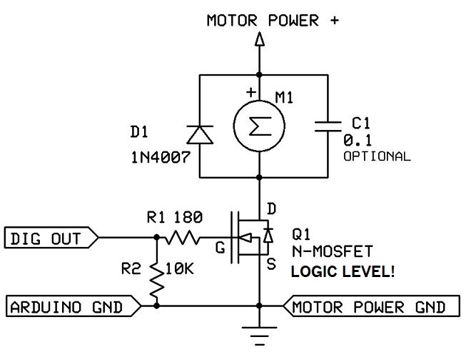
Kick-back diode is present, as you can see on schematic
It protects the Mosfet.
But it does not work in relay transition mode, and can not be attached to solenoid directly cause of system design limitations
Hence the Snubber
There's much more behind it, and DPDT relay is the only option for my particular case. I don't want to go too deep, since that's way beyond the topic of the question
In short- I do use powerfull Mosfet, and relay is only reconnecting things in two different configurations, both of which are necessary and that can't be achieved with solid state stuff
I was not seeking design optimisation or finding other ways around it, just a life time expectancy under given conditions and ratings provided
So there's absolutely no need for any guessing
Can you switch of the solenoid with the fet before switching the relay?
That would make last your relay forever...
Inductive dc is pretty harsh on the relay...
But what exactly about altering is making it different, if not zero crossing?
That's exactly what basically happens 99% of the time, cold switching under no power
But there are occasional hot switches that need to be done as quick as possible
It will see a zero crossing because as the contacts separate an arc will form, the arc will be extinguished within 10ms (UK, 50Hz) when the next zero crossing occurs. It's not the release timing that matters, it's what will extinguish the arc and how soon it will be extinguished.
I'm not sure about simply adding a diode to the contractor coil because, while a diode will completely suppress the high voltage kick from interrupting the current through the coil it will also slow the release of the contactor. Does this matter?
Second, the diode will do nothing about the arc resulting from interrupting a high DC current, that part of the problem depends only on the interruption of DC, not the inductive nature of the contactor coil. Unfortunately this is where my knowledge is limited, I would think a complete solution would comprise a diode across the coil of the contactor and an RC snubber across the contacts of the relay, but I can't suggest the appropriate values of resistor and capacitor or how to calculate them. Others might have better suggestions.
The zero crossing is the main difference but in DC, material deposits and pitting due to the arcing can also be an issue. In DC the material deposits and pitting will always be on the same contacts where as in AC it can be either.
In either case you can't infer anything from the AC ratings.