First PCB Critique Rev 1

Last year, thanks to the good people on this forum, I designed and successfully built my first PCB board to control a PWM radiator fan for a Mercedes Benz. See:

The controller uses an Arduino Nano 3.3BLE. At the time I did not know what BLE stood for and wasn’t using any of those functions. But I have since learned that I could use the BLE functions to report the three variables Radiator temperature, AC condenser temperature, and under hood temperature. The previous version had the capability of connecting 3 LED’s to blink out a binary sequence of codes to know these temperatures. Consequently the LEDs will now be inserted onto the board and just indicate the status of the three thermisters are in range as in not shorted or open.
While the current setup can do this without any physical modifications, there were other lessons learned that I would like to implement at this time. As explained below.

Connectors

The weakest link I have observed so far is the connectors I chose to do the original job. These turned out to be not adequate and failed immediately on connection. I actually found selecting connectors to be one of the most difficult jobs for the uninitiated like myself. Because I wanted this to look like a factory like installation, I wanted connectors instead of screw terminals.
The first set of connectors I chose was the TE 5-102617-6 and TE 102448-6 pair. Several issues I had with this connector set

  1. Connectors are not keyed. I could easily mate them upside down
  2. Connectors do not latch together
  3. Connectors are made for 20ga max wire. I was using 6 20ga and 1 18ga
  4. The area where the wires crimp on the TE 102448-6 connector is not supported. This became the Achilles heal and the reason I had to replace it immediately. Trying to manipulate this connector in place under the dash of the car, caused these pins to fold and break right at the point where the pin is not supported. I had come to the conclusion that these connectors were made for very light ribbon cables in computers etc. They worked on the bench But?


TE 5-102617-6 and TE 102448-6

Below is the TE 102448-6 shown installed on the Automotive wire harness.

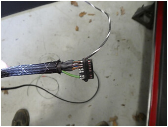
TE 102448-6 Installed

After the failure I was able to find another set of connectors that would address problems 1, 2 and 4. Problem #3 was dealt with as it was for the first set of connectors by removing a few strands of the 18ga wire so it could be crimped on to a 20ga pin. It all works reasonably well and is currently installed in the car now, however I am aware of its flimsiness and the latches are weak and it has been known to come loose.


TE 102387-3 and TE 104130-3

So now, since I don’t need 16 pins for LED outputs, I was able to find an Automotive quality connectors of 8 pins for the signal wires and 3 pins for power. These connectors are:


TE 1717412-2, TE 178289-4,TE 1-178293-2, TE 1-178288-3

Thermister Capacitors

During the development of the original board, there was a lot of critique on the way the filtering capacitors needed to be connected for the thermisters. Discussions ranged for would not work at all to it will work but it’s not the preferred solution, etc. So I did some research and found a solution proposed by a thermister manufacture, Northstar Sensors. The manufacture also proposed turning on the thermisters only when you need to take a reading. I consider the thermister manufacture to be the “horse’s mouth” if you will, so I will go with that. The article is presented here:

The circuit schematic for the current and proposed PCB is presented below. These show the difference in capacitor arrangement. The new schematic also shows a voltage sensing scheme. That will be used to tell if the engine is running or not.


The current circuit schematic as it stands today


The proposed circuit

Engine Running Sensing

It is desirable to only run the fan in this car while the engine is running or maybe for 30 seconds after shutting it off. Keep in mind this fan can draw up to 50 amps. So if you want to park the car and turn on the radio with the key on, running the fan for longer periods of time is not a good idea. The circuit can be activated in 2 ways.

  1. Sense the key on voltage and determine if it is > 13.5V meaning key is on and engine is on. < 13.5V means key is on engine is off.
  2. Sense the field in the alternator. That is kind of a strange circuit and for this car, there is an electronic indicator that I’m not sure I can implement it without jacking with the vehicles warning light system.

Input Over Voltage Protection

During the development of the old PCB input voltage regulators were suggested. I did try to implement one but found my soldering skills to be lacking for the model I tried. In any case I have been running flawlessly without it just by feeding straight ignition voltage to the Arduino Nano 33BLE. However I would like to provide some voltage spike protection to the circuit. You will see these as the 2 SLD18-018 Transorbs.

Built in LEDs

As stated before the original design had circuitry for three external LEDs which would blink out binary codes so that the temperature of each of the three sensors could be determines. It was required for these to be external because the controller mounts under the dashboard of the car. With the use of BLE communication this is no longer needed. But the three LED’s will remain fixed in the box poking through the cover and be used as a thermister circuit test when the system boots up.

Using BLE

So now that I know what BLE stands for, I fully intend to implement it so I can read the temperatures and fan speed as I’m driving. To date I can use the Light Blue BLE app to read the data but it only reads one piece of data at a time and needs me to flip pages to read each value. Not a good thing to do while driving. But with the help of the MIT App Inventor community, I’ve put together an app that reads the temperatures and fan speeds and presents it to my cell phone all on one page. So far I have only sent it dummy values to get a handle on how it works but it’s coming along.

So where am I now?

To date I have ordered all the pieces to breadboard it and try a few things out. I have just moved house so finding everything is going to be a challenge. At this point any critiques or advice is welcome.

Connectors.....
Using soldering, and appropriate connectors have the disadvantage that the solder creeps into the cable a bit and make it more stiff, and more easily brakes.
Crimping connectors don't have that disadvantage but require a special tool for crimping. Using ordinary pliers is at risk for improper work. This shows up in portable or moving equipment. The shakings, vibrations, maybe light shocks might look harmless but time takes its toe on the connections.

Soldering is not allowed for Aerospace application. My understanding is that it can be good or better than a crimp, but it cannot be inspected as readily. That being said Mercedes Benz soldered everything back in the late 80's time frame. That appears to have changed in the 90's. I do have the correct crimp tools for my task and have no issues with the crimp.

With connectors, crimping wires is far superior to soldering.

Silicone insulated 24, 26, 28 AWG stranded wires are best.

You can use this technique to use heavier gauge wires.

image

image
FYI

I have that crimper. Crimping was not my problem. The housing that held the terminals was unsupported in the crimp area and allowed the terminal to fold over at the flat section between the crimped area and the terminal. After several attempts to manipulate this around it folded over enough to finally break off. That issue has been solved with the second set of connectors I tried, but its still not an automotive solution in that the latching mechanism is not as robust as it should be and the one 18ga wire I use is really out of range for it.

As far as the wire size, I use 18 and 20ga as automotive standards. If I go down in gauge at the controller end, I end up with the opposite problem at the thermister connector end. Two of the thermisters I use are standard Delphi automotive thermisters which only mate to a automotive connector using heavy gauge automotive wiring. The third thremister I have for the condenser temperature is a standard clip on laboratory grade using fine stranded 30ga wire. For that one I have to put several layers of shrink tube on the wire to increase the insulation diameter and fold the wire over several times allow it to crimp tight to the Delphi automotive connector. That thermister will eventually be replaced with automotive grade one that screws into the AC line and uses 20ga wire. I will probably have to change a resistor for the board when I do that.

Today's task involved reworking the board. I had to replace all the components that were downloaded using the Ultra Librarian because they have problems with Eagle cad. I was getting Restrict errors. I re did everything using the Library Loader program available from Mouser and all works well.

So after re-doing everything the PCB board now passes all the tests. The latest schematic and PCB layout are presented below.


Not much more I can do at the moment until I try it out on a bread board. But getting back up to speed on all this after about 9 months has been a pretty big hurdle in itself.

The schematic is low resolution.

Try to keep all signal traces on the component side, add GND copper pour on the bottom.

That is a screen capture. Maybe I can figure out a way to save it as a PDF and repost.

Will try working the grounds to the bottom. I was planning on adding a copper pour on the top and bottom, which is what I did the last time. Should I just do the bottom? I don't show them because then I cant see the traces.

Thank You

Add GND copper pour on the bottom only.

Try to keep your cross-unders as short as possible; add top strapping over long cross-unders.

image

I got all but two ground traces underneath. I could get the longer of the two under by adding a via to bring the FANPWM signal back up, But I wasn't sure what was better overall. I added the schematic as a PDF, hopefully that helps.

Thanks
John

Fan Control With Engine On Sense.pdf (17.0 KB)

This might work on a one of a kind but It has no electrical protection for many of the processor leads, no protection for the I/O. Consider reading some information on automotive electronics, load dump etc.

Unfortunately this is an area that I'm not too familiar with and certainly open for suggestions. I have done a lot of reading but most of it is above my head. For my first PCB, I added all the filtering caps at the suggestion of this forum. I am well aware that 1 year of operation in 1 car is certainly not a robust test of electronic components. For this version I have added voltage spike protection using the two transorbs. I have opted out of using reverse polarity protection because they use critical components in series that if damaged knock out the whole system. I'm willing to take a chance without it.

The SLD18-018 transorbs are a new feature I added for this board and would appreciate comments on my implementation of them. I uploaded the data sheet.

Littelfuse_TVS_Diode_SLD_Datasheet.pdf.pdf (838.8 KB)

I also investigated using a product called Ruggeduino. I did start a thread here but it never got so far as to answer the question of how useful it was. To me it appeared that the Ruggeduino would really only protect me from mis wiring errors during development.

Thanks
John

In Transorb Hell

OK so my parts came in including the TVS Transorbs.

Something does not look right here. These things are huge. They look more like they go on an arc welder. The leads are so big they will not fit in any of my bread boards or prototype boards. So definitely looking for ideas in this area.

Other than that I have the bread board complete to the point I am fairly confident with. Basically the same circuit I had previously with only the thermister circuits filter capacitors changed.

I still need to set the LED resistors. I'm showing the LED resistors at 220Ω and I'm running the LED's at 3.3V so theoretically I can use a resistor as low as ~ 60Ω, but I have found them to be too bright. They actually blind me on the bench at full power.

That size should give you an idea of how much energy is coming down the line during some of the transients. They make regulators that have built in reverse battery protection. Also assumed it has been installed all of the other units will also see the reverse battery. There is also the 24V battery jump and yes it can be connected in reverse hence the reverse battery many at 24V. You could design your own VCC supply and easily implement the needed protection, that is what many of the OEMs do. Sldo under hood starts is about 125C or higher ambient. There are some OEMs that allow slightly lower temperature in specified areas. The best place for your module is the body compartment, that is only 85C. As you get more involved you will discover like many others before and behind you automotive electronic environment is extremely bad.

John Griffith posted this about 12 years ago, there is now a +175°C rating.

"AEC-Q100 has following Automotive Grades;
Grade 0 (or A): -40°C to +150°C ambient operating temperature range
Grade 1 (or Q): -40°C to +125°C ambient operating temperature range
Grade 2 (or T): -40°C to +105°C ambient operating temperature range
Grade 3 (or I): -40°C to +85°C ambient operating temperature range
Grade 4 (or C): -40°C to +70°C ambient operating temperature range

Typically Commercial would align with Grade 3 and Industrial would align with Grade 2 and like you said Grade 0 and 1 align with automotive. More specifically with the automotive grades Grade 0 is usually used under the hood (due to harsher ambient conditions) whereas Grade 1 is used elsewhere in the vehicle. What specifically is your target application? Where will the electronics be housed?"

Many of the fatal faults may only occur in 1 out of a thousand cars in the warranty period. Consider how many failures there would be when building several million cars each year.

Thanks for the reply

If I understand you correctly, you are saying those TVS transorbs may be the correct size for my application?

I have several constraints I have to keep in mind an one of them is the footprint of the board. Not much room to place large modules in this car. My ability to fabricate these boards is pretty much limited to through hole designs at the moment, which drives the size up.

I have been trying to design everything using 125°C rated components but the Arduino 33BLE is only recommended to 85°C, consequently it becomes the only component the forces me out from under the hood. It is currently mounted under the dash.

In my reading I have come across many of schemes for transients. Some add more and more layers to control different scenarios. The transorbs appeared to be the simplest but consequently will do the least.

This is all compounded by the fact that I will have 2 input sources. 1 for battery voltage and one for key on voltage. I can eliminate the battery source if I give up the idea of running the fan for a few seconds after the key is turned off. So using the two sources the protection needs to be implemented twice.

But I am not trying to hold reliability to 1 in 1,000,000 like we did in the aircraft industry. I would like to just keep it down to about 1 in 1000. So seeing that its been working well so far with nothing, I was hoping to just put on that first layer of protection with two transorbs. So I guess I'm not trying to keep up with Robert BOSCH but if I could at least get better than Lucas that would be good. Does that make sense?

1 Like

That is an old quality number for Automotive they are in the PPB but they had to go through that PPM level first. There is a trick and it is relative simple. Do not adsorb the transient but take the teeth out of it. A resistor in series with the signal will attenuate it quickly. There are many regulators that will do the trick, here is one: TLS203B0EJ V33, I have never used but it is an example of how to eliminate external circurity. Another trick is to use a P-MOSFET to protect against reverse voltage. Be sure to put a zener between source and gate to protect it. Purchase a few of the cheapest TO-252 devices you can afford. I found if I put solder paste on the pad then the part, holding the iron for a bit longer then comfortable the solder will melt and the device will attach. I have even just put solder on the pad with some paste. If you get this you will be able to use some of the newer power devices.

I will try to explain an input protection circuit I use a lot. Use a pull up resistor to 12V, to a connection, size the resistor to draw at least 1 mA through the connection when grounded. Then I use something in the range of 100K in series from the connection to the processor input. That will work with most processors and applying a few hundred volts will probably fry the pull up resistor before the processor. Remember these transients are powerful but live only a short time. This will give you something to think about. Most items have a pulse rating, this is the place to examine them.

You order the wrong package.

This is a little over my head but here is what I think I understand. A TLS203B0EJ V33 will not work in this application because it has a 3.3V output the Arduino 33 BLE operates between 5V to 18V. There appears to be a TLS203B0EJ V50 which will operate at 5V. Not sure how that would work operating on the lower end of the allowable range. It would be perfect id there was a TLS203B0EJ V120 with a 12 V output. OK so that might be a possibility for the Vin circuit on the Arduino. Unfortunately I have another circuit that accepts automotive input voltage that cannot be regulated. That is the circuit going to pin A0 on the Arduino in my proposed diagram. That circuit senses car battery voltage. It goes through a voltage divider to bring the battery voltage to acceptable levels for the Arduino inputs. The program will interrogate pin A0 to determine if the battery voltage in above 13.5V, ~1.2V at pin A0 after the voltage divider. V > 13.5V means the engine is running, which is important to know because I don't want the 600W fan running while I'm parked with the engine off listening to the radio. So for that second circuit I cannot use regulated voltage. In this case I need to just clip the voltage when it gets above ~16V. That was my intent with the SLD18-018 TVS Transorb.

The TO-252 is a surface mount. I did find there is a TO-251 through hole version. For the moment that would be more my speed. After my previous attempts at bridging the jumpers on a voltage regulator I tried in the last board, where I consumed 5 voltage regulators, I know I'm just not ready for surface mounting at this time.

So I believe I can figure out how to make a TO-251 work on the Vin pin of the board but I'm not sure if that will work at the A0 pin.

I do apologize that your last paragraph I do not understand as I really am not an electrical person. I'm a retired mechanical test engineer. For electrical stuff, I'm still on the monkey see monkey do stage. If you could provide a sketch that would be a big help.

Thanks John

It is what I intended to order. I ordered the model SLD18-018. Best I can tell is the Maximum Peak Pulse current is driving the size. I'm thinking possibly something in the 30A range might start to look like something that belongs in here. I will see what else I can find.

FYI

Tutorial