FIXED (Thanks): Arduino nano.. voltage divider not working.

Hello everyone!

I have a car outside with a dead cooling fan system - seems ECU related so no chance of getting that fixed easily as it's an old car from 1998! As it's a two speed fan unit, I can't use a bog standard override so I thought I'd use arduino to do it. The engine has a temp sensor in two places (known to be working) and I thought I would sample the voltage from one in order to determine when to activate the low and high speed modes of the fans (using the temp gauge on the dash as a visible reference to set up the values via my netbook).

So, here's what I have so far:

(Yes I have the relay board lol but thats not connected yet).

Arduino is hooked up to a bog standard arduino voltage divider with values of:
R1: 30k
R2: 7.5k (and yes I checked both on the meter to confirm - individually and together).

The problem is that the battery it's hooked up to for testing shows 4.21v on the meter. The meter shows 4.21v on the input to the voltage divider, and it shows 4.19v on the output of the divider... and going into the arduino on the terminal pins.

That can't be right! The output should be a fraction of the input - not the same minus 0.2v! At first I thought it was my code.. but then realised that would not account for the meter picking up a very similar voltage at the output of the divider.

So whats gone wrong here please?

I do also have a digital temp probe hooked up (previous idea was to glue that to the engine lol) but I don't see how that could affect it as thats connected to the DIO pins not any analogue.

The code seems to work fine... (ADC sample value is 969 and the usb supply is 4.46) but I'll post it to keep the critiques happy:

#include <OneWire.h>
#include <DallasTemperature.h>

// Data wire is plugged into pin 2 on the Arduino
#define ONE_WIRE_BUS 5

float Supply = 4.46;

int led = 13;
int vcc = 2;
int gnd = 12;

int analogInput = A1;
float Vout = 0.0;
float Vin = 0.0;
float R1 = 30000.0; //  
float R2 = 7500.0; // 
int Value = 0;

// Setup a oneWire instance to communicate with any OneWire devices 
// (not just Maxim/Dallas temperature ICs)
OneWire oneWire(ONE_WIRE_BUS);

// Pass our oneWire reference to Dallas Temperature.
DallasTemperature sensors(&oneWire); 

// the setup routine runs once when you press reset:
void setup() {                
  // initialize the digital pin as an output.
  pinMode(led, OUTPUT);  
  pinMode(vcc, OUTPUT);
  pinMode(gnd, OUTPUT);
  
  // start serial port
  Serial.begin(9600);
  Serial.println("Dallas Temperature IC Control Library Demo");

  // Start up the library
  sensors.begin();
  digitalWrite(led, HIGH);
  digitalWrite(vcc, HIGH);  
  digitalWrite(gnd, LOW);  


  pinMode(analogInput, INPUT);
}

// the loop routine runs over and over again forever:
void loop() {

  
  // call sensors.requestTemperatures() to issue a global temperature
  // request to all devices on the bus
  Serial.print(" Requesting temperatures...");
  sensors.requestTemperatures(); // Send the command to get temperatures
  Serial.println("DONE");

  Serial.print("Temperature for Device 1 is: ");
  Serial.println(sensors.getTempCByIndex(0)); // Why "byIndex"? 
    // You can have more than one IC on the same bus. 
    // 0 refers to the first IC on the wire
    

   Value = analogRead(analogInput);
   Serial.print("ADC Value: "); Serial.println(Value);
   Vin = (Value * Supply) / 1024.0; 
   
   Serial.print("INPUT Vin = "); Serial.println(Vin, 2);

   delay(5000);
}

Sample from the serial link:

Requesting temperatures...DONE
Temperature for Device 1 is: 26.25
ADC Value: 970
INPUT Vin = 4.22

So whats with my voltage divider not working? :confused:

Many thanks,

Twixy

You have connected the voltage divider incorrectly. Sorry I can't be more specific. Maybe if you gave us a schematic instead of a photo of the inside of your house.... Hand drawn on paper would be fine. Just don't photograph the schematic from the other side of the room!

PS. Congrats on figuring out how to post photos at all, and using code tags (even of the code you posted is kind of irrelevant). You are already way ahead of the newbies.

I don't think I have... and if I had, (eg polarities reversed) then the ADC on the arduino shouldn't be reporting a value of 970! Or should it?

anyway... this is the best I can come up with:

Battery:

  • Red wire
  • Black wire

Red wire -> Red wire
Black wire -> Blue wire

VD Input:
Red wire -> VCC
Blue wire -> GND

VD Output:
S -> White wire

  • -> Black wire

Arduino Nano:
White wire -> A1
Black wire -> GND

Don't know what you mean by "bog standard Arduino voltage divider."
Usually a voltage divider is two (or more) resistors in series connected at one end to a voltage source and to ground at the other end and the tap between the resistors goes to the sampling device.
If your divider is hooked up accordingly (you didn't specify which end the battery is connected to) you should be seeing either 3.36 or 0.84 volts unless the Arduino is affecting the divider. Have you measured the divider output disconnected from the Arduino?
Also, is your "test" battery connected to the circuit ground?

this is the best I can come up with

Then "Try again but do it better" is the best we can come up with.

(deleted)

Well I've disconnected the VD from everything and going over it with my meter I have a hunch I may have a broken track :o

Measuring between:
S -> VCC: 30k
S-> GND: Infinite
S -> R2 GND: 7.5k
GND -> - : 0
GND -> R2 GND: 0
GND -> R2+ (S) : Infinite... that disproves the dodgy ground track then!
GND -> S: Infinite
VCC -> S: 30k
VCC -> - : Infinite
VCC -> R2 GND: Infinite
VCC -> R1 +: 0
VCC -> R2 GND: 37.5k
VCC -> GND: Infinite

So how come a stupid moron like me has managed to disprove the laws of physics?

Twixy:
So how come a stupid moron like me has managed to disprove the laws of physics?

Perhaps your logic is as convoluted as your "data"?

PaulRB:
Then "Try again but do it better" is the best we can come up with.

I trust that does it for you? - found on:

Thats exactly what I have.. schematic-wise.. but here is my feeble attempt!:
http://s31.postimg.org/rs41ccpvf/screenshot_559.jpg

Due_unto:
Don't know what you mean by "bog standard Arduino voltage divider."

My bad description lol.

One of these (which can be found on ebay and google using "arduino voltage sensor"):

Due_unto:
Usually a voltage divider is two (or more) resistors in series connected at one end to a voltage source and to ground at the other end and the tap between the resistors goes to the sampling device.

Thats what it is and does on the thingy I have pictured above.

Due_unto:
If your divider is hooked up accordingly (you didn't specify which end the battery is connected to)

The VCC / GND end. I then had the S + - end connected to the arduino... with the + left not connected.

Due_unto:
you should be seeing either 3.36 or 0.84 volts unless the Arduino is affecting the divider.

I'd hope so..

Due_unto:
Have you measured the divider output disconnected from the Arduino?

Right, I've disconnected the arduino completely... and guess what I'm seeing at S: 4.19V!

Due_unto:
Also, is your "test" battery connected to the circuit ground?

No, just to the GND on the voltage divider - as shown in the above schematic.

spycatcher2k:
The only way for this to NOT work is :

Wrong value resistors in voltage divider, Voltage divider not connected properly, or not reading from the junction of the voltage dividers resistors.

Please take a close up, in focus picture of the voltage divider, showing the connections & colour codes of the resistors.

Sorry I can't get you a better close up - phone won't do it!

Something constructive would be appreciated - thanks :wink:

With only the battery connected to "Vcc" and "Gnd" of this divider board (no other connections):

  1. What is the battery voltage (with the black probe on Gnd)?
  2. What is the voltage at 'S' (with the black probe on Gnd)?

(deleted)

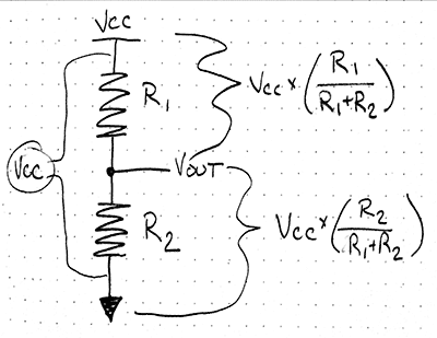
I'm sure you haven't disproven any physical theories. Get your publishing skills in order if you have though. I was completely baffled by your verbal description, but the above photo makes sense. I suspect that it's hooked up weird, or that perhaps it has some damage that we can't see. Here is a simple schematic of how a voltage divider is wired, and the voltages you should be seeing:

Are those the voltages you are seeing?

Hi Chris,

Sorry if you found my description hard to understand.. I mentioned it was a voltage divider and being an arduino forum I figured that most folks here would know that it was a premade version also known as a voltage sensor - i see them in many sensor kits on ebay so thought it was common knowledge.

Then I supplied code, output, voltages.... Oh well... I suppose it's like getting help with programming.. takes a while to get the hang of it!

Right, the measurements I have are:
R1 0V - should be 3.57v
r2 4.19V - indicating that R1 is somehow magically broken?!?!?!?!?! - should be 0.89V

When I disconnect the battery and measure the resistance it's 30k.

spycatcher2k:
What I would expect to read between :

  • and s : 30K Infinite - + on the output side (or did you mean VCC on input? - confirmed below)
  • and s : 7.5K Infinite
  • and - : 37.5K Infinite
    VCC and + : 0 Ohm Infinite - but as I understand + on the output is not connected
    GND and - : 0 Ohm Confirmed
    VCC and GND : 37.5K Infinite - with meter set to 20M :o
    VCC and s : 30K Confirmed
    GND and s : 7.5K Infinite

Can you confirm these values please. :slight_smile:

I confirm some of them.. others are totally broken it would seem.

As I understood, the + on the output side is not connected to anything though.. (begs the question.. why is it there then?)

I'm assuming from the measurements above and in my reply to chris that this board or R1 is broken?

(deleted)

Which is odd because I'm able to measure 4.19V across R2... but 0V across R1... so voltage is apparently bypassing R1 completely and dropping 0.2V on a 30k resistor!!!

But then when measuring the voltage across R2 something weird happened. For a few brief moments it displayed 0.81v - 0.84v and fluctuated a bit.. (confirmed by measuring A1 and the arduino serial link output) and then it went back up to 4.19V again.

Here is my serial output from yet another measurement a few moments ago:

Requesting temperatures...DONE
Temperature for Device 1 is: 25.44
ADC Value: 967
INPUT Vin = 4.21

Requesting temperatures...DONE
Temperature for Device 1 is: 25.44
ADC Value: 193
INPUT Vin = 0.84

Requesting temperatures...DONE
Temperature for Device 1 is: 25.44
ADC Value: 192
INPUT Vin = 0.84

Requesting temperatures...DONE
Temperature for Device 1 is: 25.44
ADC Value: 967
INPUT Vin = 4.21

So I had a hunch it may be a joint.... and having discussed this with spycatcher via PM i've attacked the SMD resistors solder joints with the iron. Just before I did that though i inspected R2 with the jewellers loupe (40x magnification) and one joint did look like it had a fine crack in it. So i resoldered that, no difference.. then did the other three and now it seems to work as it should!!!!

S = 0.84V!!!! (and holding!!!)

Arduino code is showing the correct voltages, and now i can get on with sorting out the relays so i can have working fans again!

Thank you so much everyone, even those who were a tad unhelpful.. without you all i wouldn't of had enough things to check and work it out from - and a massive thanks to spycatcher who nudged me in the right direction!

Have a great weekend!

I mentioned it was a voltage divider and being an arduino forum I figured that most folks here would know that it was a premade version also known as a voltage sensor

A what?

AWOL:
A what?

Voltage sensor... using a voltage divider

Nope; never seen / heard of one of those.

Oh ok!

There was me thinking this being an arduino forum full of electronics enthusiasts... that everyone would be well aquanted with it!

Obviously my logic is somewhat skewed!!!

Twixy:
There was me thinking this being an arduino forum full of electronics enthusiasts... that everyone would be well aquanted with it!

No, it's not a "sensor" - it's a glorified resistive ladder, a voltage divider.
It's not a reflection on you, but it's an absurdity.

I wonder how many that guy has sold. How much did you pay for it?