Floating State Input

Hello.

I am having a problem with floating input pin, more often when using it as a interrupt and on a dry enviroment. It is a MEGA 2560 with code below:

void setup () {
     pinMode(19, INPUT_PULLUP);
}
void function () {
     ...
}
void loop () {
     attachInterrupt(digitalPinToInterrupt(19), function, FALLING);
}

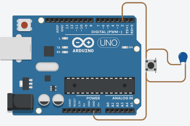
There is also also an extra 1k external pull up resistor.

I didn't see this happen before attachInterrupt() or after detachInterrupt(), but I can't say it doesn't happen. Is there any difference between a regular input and an interrupt input?

I've been searching for more info about it, but didn't find anything else but use pullup resistors. Any ideas what is going on, or how to fix it?

Note: this happens even with this pin disconnected.

Welcome to the forum

What is the problem and how does it manifest itself ?

Why ?
1K sounds too low a value and if it is parallel with the internal pullup then their combined effect will be very low indeed

What is "this" ?

Please post a schematic of your project and a sketch that illustrates the problem, whatever it is

1 Like

Then you still may have problems with a large antenna in a hostile environment. Consider adding a capacitor as well, to form a RC low pass filter for that pin.

What value for this capacitor?

Experimental, according to your environment.

I am using this extra external pullup resistor to avoid this problem (floating pin).

I will try to illustrate a little better here below:

bool stopLoop = false;

void setup () {
     pinMode(19, INPUT_PULLUP);
}

void function () {
     stopLoop = true;
}

void loop () {
     attachInterrupt(digitalPinToInterrupt(19), function, FALLING);
     while (!stopLoop){
     ...
     }
    detachInterrupt(digitalPinToInterrupt(19));
}

image

The problem I meant is that function() is been called even without pressing the button.

to form a RC low pass filter for that pin

So, you mean like this?

image

Or like this?

image

should be
volatile bool stopLoop = false;

Yes. But I see no external pullup resistor?

Yes. But I see no external pullup resistor?

Sorry, I missed this when drawing.

In resume: I need to use this schematic and change variable to volatile? Is that right?

Have you really got the pullup connected to Vin ?
How is the project powered ?

I don't recommend connecting the pull up resistor to Vin. Regardless, whether it's connected to anything or not.

     attachInterrupt(digitalPinToInterrupt(19), function, FALLING);

Should be in setup() not loop().

Also please don't tell me you have Serial calls in 'function()'...

What are you really doing? What does this project do?

There is no need to ever detach an interrupt, especially in the loop function which starts with attaching an interrupt pin. And even this should not be in the loop function but in the setup function.

Also bush buttons like this should be wired across the diagonal to prevent any doubt about the orientation of the switch.

We only know what you tell us about your project d you are telling us very little. And half of what you have told us is wrong.

This code has 995 lines, so I am trying to simplify here.

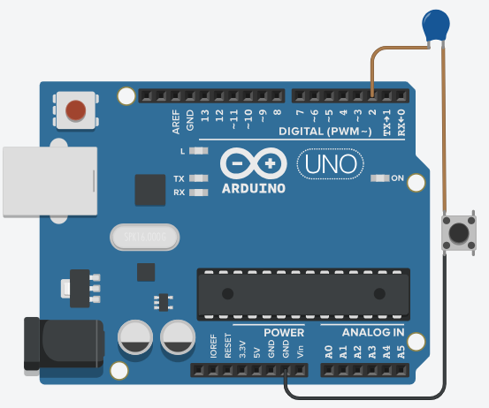
Also, I am using a MEGA, not a UNO, but for schematic, I only have Uno availabe.

This project controls a step motor, a 16x2 Display and some other logics as well. stopLoop_funtion() has nothing more then those two lines.

I use detachInterrupt() because this button will be used to something else when this loop does not occur. It is in fact a CANCEL button on a keyboard, so it must to cancel this loop, but also navegate through menus.

volatile bool stopLoop = false;

void setup () {
     ...
     pinMode(19, INPUT_PULLUP);
     ...
}

void stopLoop_funtion() {
     stopLoop = true;
     digitalWrite(13, LOW);
}

void loop () {
     ...
     attachInterrupt(digitalPinToInterrupt(19), stopLoop_funtion, FALLING);
     stopLoop = false;
     while (!stopLoop){
     ...
     }
     detachInterrupt(digitalPinToInterrupt(19));
     ...
}

So the way you do this is to write a minimal example that shows the problem, and then post all the code and a proper diagram.

So, nothing in any of the "schematics" you posted was correct.

If you use pencil and paper for the schematic, a square can represent any microprocessor. Label the pins, parts and connections clearly and correctly.

Hello guys.

First of all, sorry for this miss explained draws, I will try to be more clear from now on.

I have an update on this case. Let me show you the real circuit I am using:

At first, I tryed to use only one 100uF capacitor, but it was still floating too much, so I added a new capacitor, making an equivalent 570uF. If I am not wrong, it should be 1k * 570u = 570ms to discharge the capacitor. This seams incredibly high value, but belive it or not, the pin 19 is still floating!

Facing this situation, I decided to use the code below:

volatile bool stopLoop = false;

void setup () {
     ...
     pinMode(19, INPUT_PULLUP);
     ...
}

void stopLoop_funtion() {
     stopLoop = true;
}

void loop () {
     ...
     attachInterrupt(digitalPinToInterrupt(19), stopLoop_funtion, FALLING);
     stopLoop = false;
     while (!stopLoop){
          ...
          if (digitalRead(19)) stopLoop  = false;
     }
     detachInterrupt(digitalPinToInterrupt(19));
     ...
}

This way, I check if button is pressed when while loop reaches it's end. I fell this is not the correct solution, because if pin floats at this point, interrupt will be executed. It might be 99% fixed, but I want to fix it 100%.

Any suggestions?