Hi guys, Newbie to the forum, sorry if I made mistakes.
Been working on a simple spectrophotometer project for some time now involving a photodiode transimpedance amplifier (TIA) and a 6V LED and I've made a lot of headway.
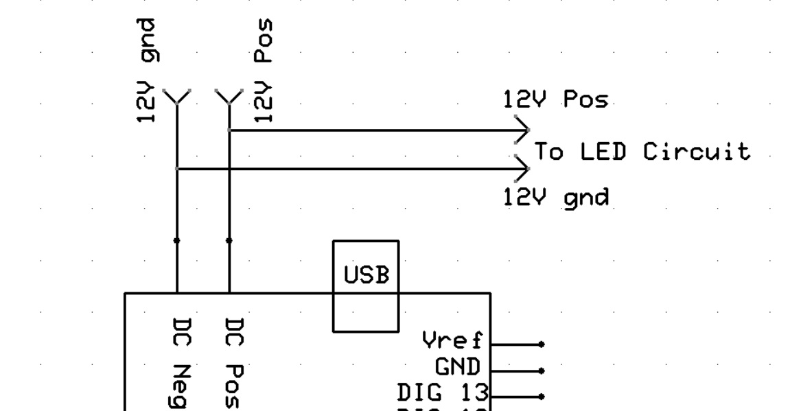
The arduino is powered from a 12V 1.5A switched mode power supply connected to the DC jack. I choose 12V because I'm utilizing an LM317 set up as a constant current source to precisely drive the LED at 60mA and the design specifies it needs a decent amount of head room above the LED drop voltage. I source the 12V directly from the Vin pin bypassing the arduinos 5V regulator.
I'm then powering the TIA photodiode circuit composed of a LMC6062 from the arduinos 5V pin.
I recently noticed when connecting my oscilloscope to the 5V that it changes from anywhere between 4.88V-4.6V every time I turn the LED on an off again which would explain the inaccurate readings I've been recording from the TIA connected to the analogue input. The voltage is different and seemingly random at every on/off cycle.
Any insights into what could be causing this? Am I misusing the Vin pin in this way and haven't accounted for something? I assumed the 1.5A supply was sufficient to supply both the arduino and the current source. Have I ruined the voltage regulator maybe?
Notes:
An LCD display is also connected to the arduino (the standard one that comes with the starter kit)
I decreased the current source to 37mA and still obtain the same problem.
The 5V power seems somewhat noisy on the scope (I'm measuring 20-30mV peak to peak) and sometimes minor oscillations are observable
The 12V power also drops from 11.56 to 11.44V when the LED is on but this is consistent and the signal has little to no noise.
Can you provide a schematic of how everything is hooked up. Also how is the wiring done, are you using jumper wires in a testing configuration, or something more permanent like soldered wiring?
I may have missed it reading through your post, which type arduino are you using?
Forgot to mention it's an Arduino Uno. Yes mainly jumper wires. The current source and some connections for the LCD display (resistor, pot, 5v connections) are wired on a breadboard. TIA circuit is the only soldered part. Ill try provide a schematic soon, but its a bit messy so might take a while.
Here's a crudely sketched schematic, hopefully its alright. Not sure if the order of parallel connections matter in these drawings. Either way on the actual breadboard the Jumper wire to the TIA Vcc is the first connection contrary to the sketch.
Show us the breadboard setup.
Does the TIA have it's own ground connection to the Arduino (not shared with LED/LCD ground).
I don't see any decoupling on the LM6062's supply.
The Uno has a ratiometric A/D, so no good to measure "voltage" from a TIA.
You can fix that by connecting the Aref pin to the 3.3volt pin, AND use this line in setup(). analogReference (EXTERNAL);
Must do BOTH, otherwise you will damage the Uno
Now 0-3.3volt from the TIA returns 0-1023, and this should now be independent of Arduino's VCC.
Leo..
Thanks for the Suggestions
The TIA does have its own ground connection directly to the Arduino.
I had planned to add bypass/decoupling to the LMC6062 supply next. This will only remove noise and oscillations from the LMC6062 supply voltage and not address the main problem though correct? Is a 0.1uF ceramic parallel with a 1.0uF ideal for decoupling/bypassing?
Could you please explain your comment on ratiometric A/D and why this is not good. My understanding is the ADC by default compares the input signal to the 5V from the Arduino's regulator which I thought was ideal since I'm also powering LMC6062 from the same 5V so the saturation points should line up so that the op amps max output is also the ADC's max.
If the 5V to the LMC6062 is fluctuating wont it's output fluctuate regardless since it's dependent on its VCC?
Also if the 5V from the regulator is fluctuating wont the 3.3V also fluctuate since the 3.3V regulator is supplied by the 5V.
Apologies for the many questions.
Are you saying to connect the SMPS to the current source parallel to a separate 5V regulator then supplying 5V to the Arduino plus the LMC6062.
I'm considered this. It would be annoying though since I would have to cut more holes in the chassis for a separate barrel jack connection.
Or did you mean an alternative configuration?
Output of a ratiometric A/D depends on input voltage AND reference voltage,
which is good if you are using a ratiometric sensor that also has it's output depending on supply voltage. Supply variations then cancel each other out.
But the output of a TIA is not ratiometric. It's output only depends on photo current.
For that you need an absolute A/D (with a stable reference voltage).
The easy way, without adding extra parts, is to use the 3.3volt supply of the Uno,
because it's stable and not used for anything else.
Clipping (1023) of the A/D now occors at 3.3volt, which shouldn't be a problem.
Leo..
Thank you Wawa I understand now.
I just tested the 3.3V pin and it is indeed stable apart from minor 2kHz oscillation. Should I connect a bypass capacitor as well when connecting the 3.3V to AREF?
I still curious though why the 5V pin fluctuated in the way I observed. Is this normal behavior from the Arduino?
Would a better solution be to connect an external 5V regulator to the AREF pin? I think this would remove the risk of inputting greater then 3.3V into the analogue pin, as my current TIA circuit is set up to output 5V at max irradiance. I guess I could just decrease the LED current as well.
Hi,
Connect the wire that is on Vin and the gnd for the LED circuit, directly to the 12V 1.5A supply.
This will keep all of the LED current away form the UNO pcb tracks.
The LM317 is dissipating ( 12 - 6 ) x 0.06 = 0.36W, depending on the package of the 317 that should be okay.
I didn't want to rush to soldering wire onto the Arduino's barrel jack pcb connections so I instead opted to use a female barrel jack socket and have connected that to the current source on the PCB and then powered the Arduino with the 12V through the Vin pin. Would this have the same effect?
I tested this setup and I'm obtaining the same fluctuating effect as before although seemingly less so (hard to tell very random).