Fridge control project

Hello everyone, I have a project to replace the electronic board of my refrigerator ( KSU445206J 127AC) using Arduino or ESP32, and I would like to know if there is anything wrong/missing in my project. This is the first time I am working with electronics.

Here is a photo of the project diagram, sorry for the poorly drawn picture, it's my first time using GIMP on Linux.

I wanted to use the FOTEK SRR 40A as a relay, but most of the ones I found to buy are counterfeit (they may have 12A triacs instead of 40A, as a reference the triac from the original refrigerator board is 16A), so I decided to use the "Sla-05vdc-sl-c" relay instead. I also decided to use relays with higher amperage to ensure that the inrush current does not damage the relay (unfortunately I don't have an amp meter to test).

I may need to use the "Sla-05vdc-sl-c" with the third electric resistance as well, because I am concerned about the inrush current.

The fan and DC motor each have their own transformer.

The SSR that control the fan, motor and resistance is the relay module Model: FC-82 which contains 4 G3MB-202P relays

The 100nf capacitor for noise filtering was recommended here:

I have a big question, as you can see in the photo in the part with a question mark symbol, the original board knows when the doors were open by looking at when the lights were turned on. On the original board, there is a 473k resistor after the pin that received this signal from the lights. Looking at the diagrams, it seems that the phase wire goes to this pin? But I don't know how I can make this work with the ESP32/Arduino, any tips?

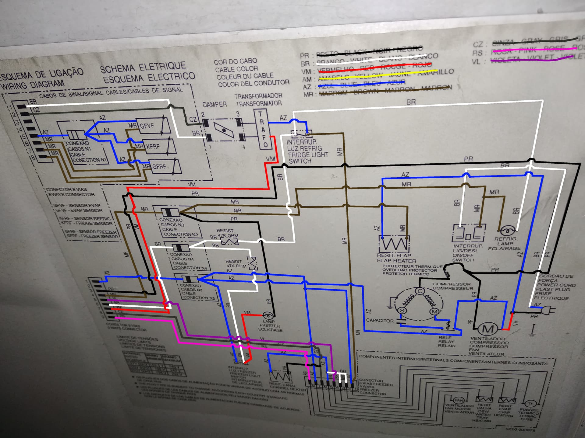
Here is the refrigerator diagram in case it is necessary:

I will work on the programming part later, I just wanted to make sure the hardware part is good.

Thank you for your help!!

are you handle comfortable with any of this pictured devices?

i know that working with mains is dangerous, but i willing to give it a try.
I never worked with the pictured devices.

make me a favor - pls stay alive. first, learn to handle every part as single. and then put it together one by one, ok? for getting help purpose is it very nice if schematic made with following some few rules. not all people have enough time to spend by examining your project but standardized schematic is much better to read.

1 Like

"earn to handle every part as single", yes, of course.
"schematic made with following some few rules", sorry about this, my objective posting here was to find a glaring error or something on the design, that people would spot right on.
"enough time to spend by examining your project but standardized schematic", yeah, sorry about that, in the future i would do a better one, if i don't get enough feedback here.

ok, if your mind, post here what you got learn and you will get feedback, no problem

Having no experience nothing can be wrong, can it?

Jesus Christ.....

1 Like

Any real project that uses Songle relays means you will be replacing them quite often. Just history reference.

i am powering the SSR, electromechanical relay and the level shifter using the same 5v power supply, there is a problem with that?

the way the NTC's are being read, i have found a example using only one, so i don't know if they can share the power supply and ground like the tree i have to read.

just forget what you think about, it is wrong. talking later about.

show schematic. piece of paper and pencil.
"easyEda.com" can help with it. pls no Fritzing or Tinkercad.

Having no experience nothing can be wrong, can it?

That's why i am asking here, in the project guidance forum, and i would test everything, not run the project from the get go.

Jesus Christ.....

Haha, i am not going totally blind.

I just saw that you repeated your post in the Portuguese language category.

Do not do this. It is against forum rules.
Ask a moderator to gather your threads.

"Controlando uma geladeira

The resistors are there to limit the heat and light from the bulbs. Just enough light to make stuff visible. I doubt they really mean 473K Ohms. Better measure! Are the lights incandescent or LED?

really? damm, thanks for that, i don't have many alternatives, most are counterfeit fotek, or cheaper songle's, but i will try to find another one.

Maybe necessary.

Could you take another photo of that? Try to make the camera view line perpendicular to the diagram; try to get the entire diagram in the picture and in focus. Check to see you can zoom in an read all the details.

TIA

a7

Humm, i was following this tutorial.

thanks, i will translate my schematic to the easyEda.

Humm, i though maybe would be some people that wouldn't know English, but i will follow the rules.

Haaa, i see.

I measured again to be certain, 478KΩ it reads in the multi-meter, i checked the colors and it makes a 470KΩ.

ops, forgot to say it is incandescent .

hahaha.

sadly the fridge radiator is in the way, i disconnected some bolts to move the radiator to be able to take that picture, but i don't think it was safe to move the radiator much, could bend some pipes.