Need some tips on what to look for with this silly problem.
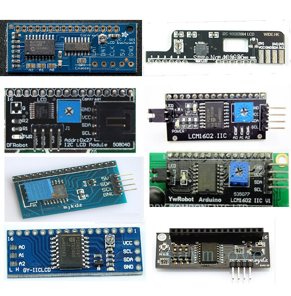
I have a simple LCD 162A (16x2) connected to an I2C controller backpack using PCF8574 chip. This is hooked up to the Arduino Mega I2C pins.
When I run the I2C scanner code, it correctly identifies the I2C controller at address 0x27.
But for the life of me I cannot get the LCD to display anything. I tried with two displays. One turns on the backlight as soon as it powers up (before uploading the code) and then nothing. The other does not turn on the backlight on power up and then nothing again.
The code is reproduced below and is as simple as it can get.
#include <LiquidCrystal_I2C.h>
// set the LCD address to 0x27 for a 16 chars and 2 line display
// address checked with I2C scanner
I agree with david_prentice. The hd44780 library will make things much easier for you.
For an I2C LCD display to work, the I2C address and the I2C backpack to LCD pin mapping must be correct. If the library default settings for either or both are not correct the LCD will not work. You can try to figure out the right pin mapping and use an I2C scanner to find the address, but if you install and use the hd44780 library that is done automatically by the library.
Install the hd44780 library. The hd44780 library is the best available for I2C LCDs. The library is available in the Library Manager. Go to Library Manager (in the IDE menus, Sketch, Include Libraries, Manage Libraries) and in the Topics dropdown choose Display and in the Filter your search box enter hd44780. Select and install the hd44780 library by Bill Perry.
The class that you want to use is the hd44780_I2Cexp class. There are examples to show how to use the library. The nice thing about the hd44780 library is that it will autodetect the I2C address and the I2C backpack to LCD pin mapping.
In the examples, there is a diagnostic sketch that will help us to help you if you still have trouble with the display. Run the diagnostic sketch and post the results.
Thank you for taking the time to offer suggestions.
I tried the hd44780 library and ran their diagnostics sketch. Tried with 2 different LCDs but the same backpack. One LCD turns on the backlight on power-up (Even before uploading the sketch) and the other one does not. But after that both of them do not show any characters on the display. The output from the diagnostics is as below.
Reported Arduino Revision: 1.8.12
CPU ARCH: AVR - F_CPU: 16000000
SDA digital pin: 20
SCL digital pin: 21
Checking for required external I2C pull-up on SDA - YES
Checking for required external I2C pull-up on SCL - YES
Checking for I2C pins shorted together - Not Shorted
Scanning i2c bus for devices..
i2c device found at address 0x27
Total I2C devices found: 1
Scanning i2c bus for all lcd displays
LCD at address: 0x27 | config: P01245673H | R/W control: Yes
Total LCD devices found: 1
LCD Display Memory Test
Display: 0
Walking 1s data test: PASSED
Address line test: PASSED
Each working display should have its backlight on
and be displaying its #, address, and config information
If all pixels are on, or no pixels are showing, but backlight is on, try adjusting contrast pot
If backlight is off, wait for next test
Blinking backlight test: to verify BL level autodetection
If backlight is mostly off but
you briefly see "BL Off" on display with backlight on,
then the library autodetected incorrect BL level
and the library cannot autoconfigure the device
So, I discovered that the library uses these defaults for the LCD pins
#define EN 6 // Enable bit #define RW 5 // Read/Write bit #define RS 4 // Register select bit #define D4 0 #define D5 1 #define D6 2 #define D7 3
Whereas my LCD has the following pinout (16 pins numbered 1-16 : NOT 0-15)
1 – VSS
2 – VDD
3 – VO
4 – RS
5 – RW
6 – EN
7 – D0
8 – D1
9 – D2
10 – D3
11 – D4
12 – D5
13 – D6
14 – D7
15 – A
16 – K
So I used the following for the constructor (note I numbered pins starting from 0 since the default settings in the library are using numbering starting from 0
The last pin mapping you tried with the newLiquidCrystal library matches the pin mapping that I2CexpDiag detected.
The only difference is that since did not provide any backlight information in the constructor the newLiquidCrystal library won't allow controlling the backlight and due to the way the code works, it will set PCF8574 pin P3 (which is hooked to the backlight control circuit) to low.
If your backlight is on with that constructor, then the active level is LOW.
I2CexpDiag detected the active level as HIGH.
You should have seen the backlight blink with I2CexpDiag and you should have seen something on the LCD display as indicated in the I2CexpDiag output messages.
The real mystery is how to use the same backpack with two different LCDs.
Soldering to the first LCD is easy. Unsoldering the backpack (for testing the second LCD) is painful.
david_prentice:
The real mystery is how to use the same backpack with two different LCDs.
I have a few LCDs that I have soldered a 16 pin female header so it can be swapped between a few different backpacks.
It is actually needed/required on a few backpacks as they have the address jumpers on the side of the backpack that faces the LCD module.
I have one backpack that uses a 3 pin surface mount dip switch on that side so it also needs the header as there is no way to solder it directly to the LCD since it won't physically fit that way.
And a few have put the pot on that side (really dumb).
On those, I move the pot to the other side of the backpack to solder the backpack to the LCD.
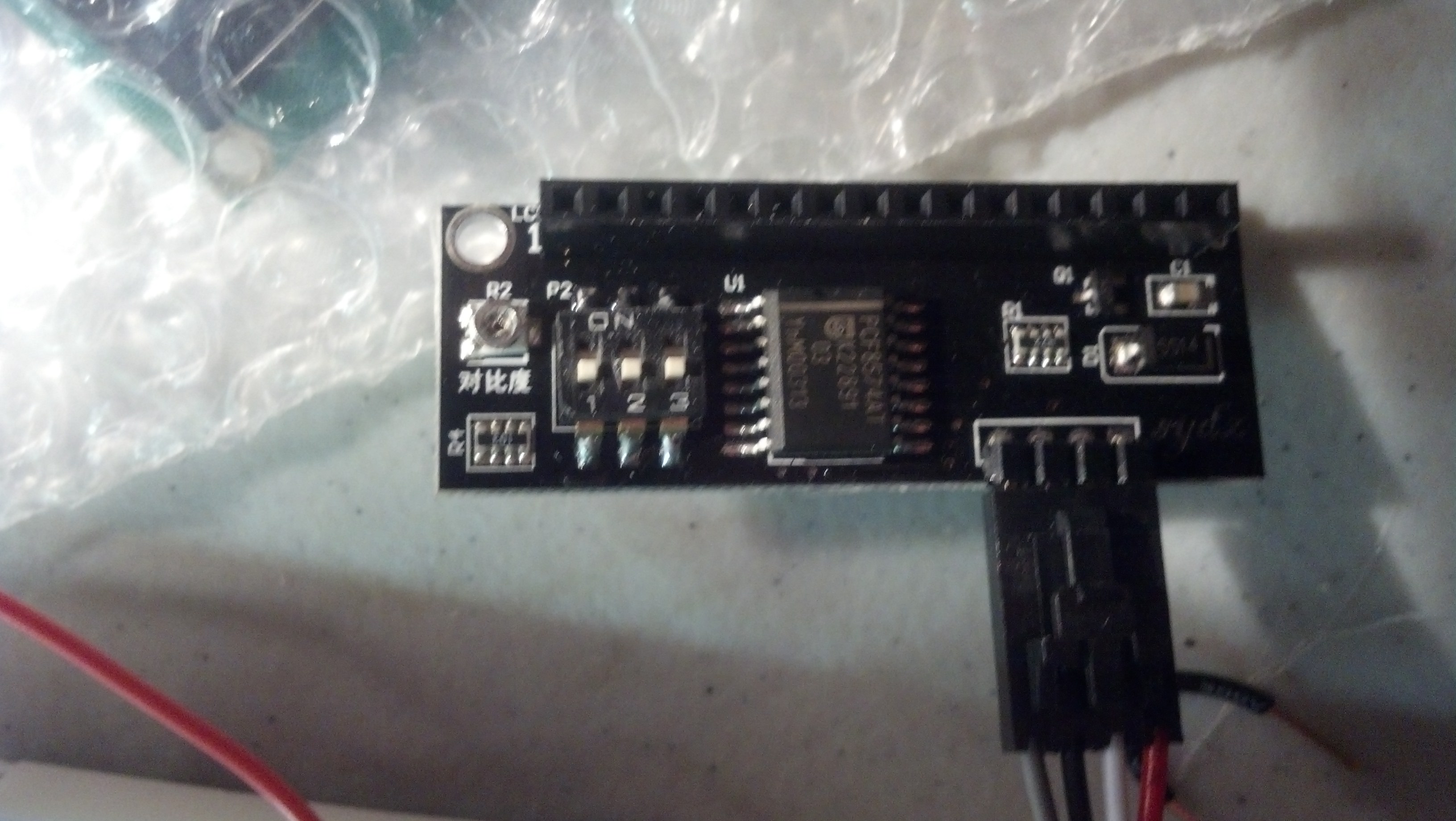
There are some really bad/dumb i2c LCD backpack designs out there.....
The sydz is by far the worst layout and design.
It uses a surface mount dip switch - so the backpack can't be soldered directly to the LCD
It has a surface mount pot on the side that would not be accessible if it were soldered to the LCD
It uses an FET so backlight auto detection by hd44780 will not work correctly.
bperrybap:
The sydz is by far the worst layout and design.
It uses a surface mount dip switch - so the backpack can't be soldered directly to the LCD
It has a surface mount pot on the side that would not be accessible if it were soldered to the LCD
It uses an FET so backlight auto detection by hd44780 will not work correctly.
Mind you, the FET is only a problem for your auto-detect code, otherwise it is an improvement.
It can be soldered directly to the LCD. but you would be attaching it so it extends above the LCD. This is not quite as bad as it seems, since five of the others show the same stupid design fault - the I2C connectors project from the wrong end of the board causing the "Dupont" fitting to project out the side of the assembly.
The I2C connector should be on the pin 16 end of the board so that the wires fold under the LCD.
Yes an FET is actually better.
Although I actually misspoke on the SYDZ board. I went back and looked at it.
It is the SY1622 backpack that has the FET.
The SYDZ board actually has what I consider to be a broken backlight circuit.
They wired it up in a common collector configuration.
The collector is wired to VCC and the backlight load is between the emitter and ground.
This forces the base current to go through the backlight rather than straight to ground.
This "works" just not as well as when wired in common emitter configuration
where the backlight load is between VCC and the collector.
They also added a separate pullup on the base of the transistor.
I'm guessing this was necessary because the weak pullup on the PCF8574 use to create the high signals couldn't provide enough current to get enough gain from the transistor to get the backlight to turn on very bright.
This added pullup is not needed when the backlight is wired up in common emitter mode.
A side effect of all this is that with the pullup on the base, it won't to allow the hd44780 backlight level detection to work correctly.