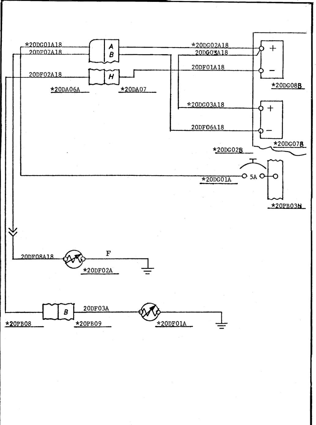
Hello, I have a fuel gauges from 1969 that I would like to replace with a digital display. I have attached the schematic to this post.
I would like to keep the original fuel level senders and wiring and just Replace the actual gauges. In the diagram, the gauges are part numbers *20DG08B and *20DG07B.
I would appreciate any guidance on this project thank you.
Rather than making us all do it again, please share the results of your research into the nature of the signals that these "senders" provide, and how they are used by the traditional gauges to show the levels.
Then we can talk about the things you know less about.
Fuel gauges are normally a kind of cross between an Current meter and a Voltage meter. Basically a really bad one of either. They have a fair resistance. Whereas ideal voltmeters have an infinite resistance and an ideal Ampmeter has no resistance.
For a Fuel gauge you want to make sure that not to much current flows to prevent the sender getting hot, and not to much voltage across the sender to prevent small sparks.
The sender is just a variable resistance, where the direction varies per type. Both occur.
The simplest solution is to leave the original gauge in place and measure the voltage between the cross of the sender & gauge. And simply check the result with a full and empty tank. I do suggest you adjust / convert it to a voltage that is suitable for the ADC that you intend to use.
Measure the resistance of your gauge.
Put an equal resistor in it's place. Might need a power resistor... (maybe 5 W or more) . Usually gauge and sender are in series from plus to chassis. But chassis may also be plus in some brands/types.
Measure voltage over resistor or over sender and translate to %full.
Read about how to protect your arduino from overvoltage, reverse voltage, emf in car environment...
By the way... why replace the most beautiful part of 1969 car?
You can also leave gauge in place and add the digital display elsewhere.
How are you going to compensate for the shape of the tank. Also how will you compensate for fuel slosh (the fuel is moving and splashing when the car is moving).