Yep - the doppler ultrasonic sensors used to be a big problem with home heating systems - the heat "blob" that would rise up when the heat came on (or caused the curtains to move) would often trigger those (same problem with depth sounders when you are in water that either has a salinity change or significant thermocline - the sound reflects off the change in density giving all sorts of wrong readings). :o
Thanks everybody for the input! I've tried using different frequencies 25kHz, 31.7kHz, 3.9kHz, 980Hz, 490 Hz, 245Hz, 122Hz, 30Hz, but none did the trick neither with TIP120 nor with IRF540N. The only difference was that at 25 and 31 kHz the fan's motor makes a lower frequency (audible) noise and writing values lower than 310 to PWM pin opens the transistor completely.
Here's the code for reference (source):
int fanSpeed = 320;
int step = 1;

// PWM output @ 25 kHz, only on pins 9 and 10.
// Output value should be between 0 and 320, inclusive.
void analogWrite25k(int pin, int value)
{
    OCR1A = value;
}

void setup()
{
    // Configure Timer 1 for PWM @ 25 kHz.
    TCCR1A = 0;           // undo the configuration done by...
    TCCR1B = 0;           // ...the Arduino core library
    TCNT1  = 0;           // reset timer
    TCCR1A = _BV(COM1A1)  // non-inverted PWM on ch. A
           | _BV(COM1B1)  // same on ch; B
           | _BV(WGM11);  // mode 10: ph. correct PWM, TOP = ICR1
    TCCR1B = _BV(WGM13)   // ditto
           | _BV(CS10);   // prescaler = 1
    ICR1   = 320;         // TOP = 320

    // Set the PWM pins as output.
    pinMode( 9, OUTPUT);
}

void loop()
{
    analogWrite25k(9, fanSpeed);
    if ((fanSpeed - step) < 0) {
      fanSpeed = 320;
    } else {
      fanSpeed -= step;
    }
    delay(1000);
}
And just to make sure we're on the same page: I'm PWM'ing the fan using transistor on low-side, fan has 3-pin (3rd pin is tach).
antti_s:
I've unintentionally just proved, that gate pull-down resistor is a must for IRF540N.
Setup: 9V PSU, positive to fan, negative to FET's source, fan's negative to FET's drain. Now if I promptly touch the gate with my finger, FET closes completely and if I touch with my finger for a second – it opens completely.
Can anybody explain why I can do that with my finger, given that I'm not touching anything else?...and with pull down resistor the abovementioned scheme doesn't work.
Have you ever touched the input terminal on an amplifier? You should hear a loud buzz. Your body acts as an antenna to line frequency and other electrical noise.
Also, static electricity. All you have to do is move and you generate static charge. If that happens to be positive, it will turn the MOSFET on, if it happens to be negative, it turns it off.
But in doing so, you are likely greatly exceeding the rated gate voltage and damaging the MOSFET.
gpsmikey:
It is not that the IRF540 will not work at all, it will work "somewhat" with a 5v gate drive. Unfortunately, the "somewhat" mode puts it in a linear mode instead of switch, so you end up dumping a fair amount of heat with the FET if you are handling any current (as well as dropping a significant part of the voltage to the part you are driving). For many of the older ones, there are direct 5v drive equivalent parts - such as the IRL540 - same thing for the old IFR520 and IRL520 (note the change from an "F" to an "L" in the part number), however, as Mark points out, there are many newer and better parts available these days that are still very reasonably priced. It is a bit harder to find 3.3v drive parts not in a SMD package, but there are some out there.
Forget this "somewhat", some devices will not work at 5V at all, the spread in threshold voltage is a whole
2V, some devices will not work at 5V. Threshold voltage is something that changes with time too,
so you may have a 'somewhat' circuit that works 'somewhat' of its lifetime - this is more problem than solution.
The plateau voltage, which is where high-current conduction starts, is well above the threshold voltage, perhaps
twice as big. You want your gate on-voltage to be nearly twice the plateau voltage for good symmetrical
switching.
Non-logic-level devices have threshold, plateau and nominal gate voltages of about 3, 6, 12V
Logic-level ones are about 0.75, 2.5, 5V
So use logic-level devices only from 5V logic.
So the FETs I've ordered finally arrived and that made me even more puzzled. After reading the datasheets I've decided to go with the logic level N-fet which can handle most current without heatsink – IRL2505 and here's the thing – it doesn't fully open at 5V at gate, whereas the old IRF540 does open.
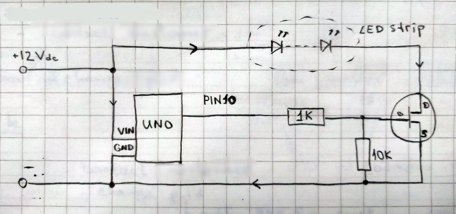
I've tried the following setup: FET gate connected to Arduino PWM pin via 1K resistor, on drain PIN there's a 10K pull down resistor. Load a LED strip.
Program writes in loop values from 0 to 255 to PWM pin.
IRF540: linear increase in brightness all the way from 1 to 255. At 255 strip is at its full brightness.
IRL2505: inconsistent increase in brightness. Could go in linear way e.g. from 1 to 20, then 21 would suddenly be dim, 22 brighter, 23 again dim and so on. At 255 strip visually around 50-60% of its brightness.
What am I doing wrong?
antti_s:
What am I doing wrong?
Show your circuit and state the modulating frequency that you're using.
You may have it wrongly connected. It may also be an issue with how you are driving it, given that the new mosfet requires more than 3 times the amount of gate charge than the previous one.
Hi,
I've tried the following setup: FET gate connected to Arduino PWM pin via 1K resistor, on drain PIN there's a 10K pull down resistor. Load a LED strip.
Err.. pull down resistor should be between gate and source, with sounce to gnd for a N Ch MOSFET.
Drain goes to one side of load and pos supply to other side of load.
Can you please post a copy of your circuit, in CAD or a picture of a hand drawn circuit in jpg, png?
Thanks.. Tom.. ![]()
TomGeorge:
Hi,Err.. pull down resistor should be between gate and source, with sounce to gnd for a N Ch MOSFET.
My bad in description, of course I've meant gate pull down resistor, thanks for noticing! Here's the schema:
antti_s:
Here's the schema:
And the modulation frequency is?
If it's anything even close to the 25 kHz that you mentioned previously then that circuit has no chance of working.
You're trying to transfer about 90 nC of gate charge at a rate of about 2 mA. It's going to take about 40 microseconds to turn on and another 40 us to turn off. I wouldn't attempt to modulate it at anything over 1kHz with that circuit.
Hi,
it doesn't fully open at 5V at gate, whereas the old IRF540 does open.
What do you mean by open?
The MOSFET switches ON with 5V on the gate and OFF with 0V on the gate with respect to the source.
If you disconnect the 1K from pin 10, what happens to the LEDs and what voltages do you get on the gate and drain of the MOSFET with respect to gnd?
Can you post a picture of your project so we can see your component layout?
Thanks.. Tom... ![]()
In English (but not many other languages) "open circuit" means infinite resistance, "closed circuit" means zero ohms. This is completely different from an open or closed water tap, for instance, its from the opening
and closing of the switch contacts. We always say "on" or "off" for a load to avoid confusion.
antti_s:
My bad in description, of course I've meant gate pull down resistor, thanks for noticing! Here's the schema:
Use 150 ohm gate resistor, not 1k, it will be somewhat quicker, but for high speed PWM you require a MOSFET
driver chip which can happily drive a highly capacitive load. Typical gate drive currents are 100mA to 1A, by
the way, but note these are transitory currents only.
Your symbol is a J-FET, not a MOSFET. Any MOS transistor or device has the MOS capacitor explicit in
the symbol.
Thanks for the answers and sorry for the confusions I've made. So to answer the questions:
- Frequency should be the default 500 Hz, though I'll double check it later
- By "open" I've meant ON
- Sorry about the symbol, I was drawing the sketch in a hurry and didn't take time to check the exact symbol I need

As for the photo, I can add it later if required, but at this point the whole thing is basically temporary assembled on a breadboard.
I've tested everything again with a another Arduino UNO board and 150 Ohm resistor between gate and Arduino pin. No luck, tried different PWM pins – same result: FET doesn't turn ON completely and gets quite hot.
Arduino PWM pin voltage is 4.86V in my case.
antti_s:
I've tested everything again with a another Arduino UNO board and 150 Ohm resistor between gate and Arduino pin. No luck, tried different PWM pins – same result: FET doesn't turn ON completely and gets quite hot.Arduino PWM pin voltage is 4.86V in my case.
Have you tested it with a static high level (no pwm) on the output pin?
Hi,
Can you post a picture of your project so we can see your component layout?
Did you disconnect the controller pin and the 150 Ohm and measure the voltages on the gate and drain with respect to gnd?
Can you disconnect the controller pin and the 150 Ohm and connect the gate to 5V and measure the voltages on the gate and drain with respect to gnd?
Thanks.. Tom.. ![]()
stuart0:
Have you tested it with a static high level (no pwm) on the output pin?
Nope, will try that today.
TomGeorge:
Can you post a picture of your project so we can see your component layout?
Sure, I'll post that later today.
TomGeorge:
Did you disconnect the controller pin and the 150 Ohm and measure the voltages on the gate and drain with respect to gnd?
Not exactly, I've just taken Arduino without anything connected to it and measured pin to gnd voltage.
TomGeorge:
Can you disconnect the controller pin and the 150 Ohm and connect the gate to 5V and measure the voltages on the gate and drain with respect to gnd?
I've tried doing something like that: instead of Arduino's PWM pin, I've connected Arduino's 5V pin to the gate via 150 Ohm resistor. The LED were flickering. I'll give it another try with a separate 5V PSU connected to the gate without resistor.
antti_s:
I've tried doing something like that: instead of Arduino's PWM pin, I've connected Arduino's 5V pin to the gate via 150 Ohm resistor. The LED were flickering. I'll give it another try with a separate 5V PSU connected to the gate without resistor.
It sounds a lot like a bad connection somewhere to me.
BTW. Have you re-tested the led strip (without the mosfet) to make sure that it's not damaged?
antti_s:
Nope, will try that today.
Sure, I'll post that later today.
Not exactly, I've just taken Arduino without anything connected to it and measured pin to gnd voltage.
I've tried doing something like that: instead of Arduino's PWM pin, I've connected Arduino's 5V pin to the gate via 150 Ohm resistor. The LED were flickering. I'll give it another try with a separate 5V PSU connected to the gate without resistor.
Did you measure the voltage at the gate and the drain when you were switching the MOSFET ON and OFF?
Make sure you have the 10K from gate to source connected ALL the time.
Also measure your 12V supply when you switch ON and OFF?
What is your 12V supply?
A picture of your project will help, so we can see your layout.
Thanks.. Tom... ![]()