I'd like to use a MOSFET in my circuit (as a switch) but I'm just not sure about something in the datasheet of the MOSFET I plan to use.
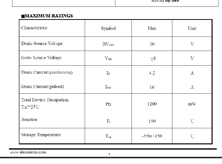
As you can see, in the maximum ratings panel, it says that the maximum gate-source voltage is around 8V an that maximum gate threshold voltage is 1.2V.
Does all this mean that it takes 1.2V to saturate the transistor and that from 8V, there is a risk of burning the transistor?
I ask this question because I would like to control the gate with arduino pins (which are therefore at 5V).
Thank you already to those who will take the time to answer
You can check the datasheet screenshots here (the images don't load):
It would be easier to just tell us which mosfet you're using. We can look up the datasheet.
Anyway, the threshold is the gate voltage at which the mosfet just begins to conduct. The voltage at which it's fully turned on will be significantly higher than that, and depends on the voltage and current you need to switch, the temperature, etc. But I think a mosfet with a threshold that low would certainly work with a 5V Adruino, and even a 3.3V Arduino.
ShermanP:
It would be easier to just tell us which MOSFET you're using. We can look up the datasheet.
I'm using the SL2300.
I have another question. Could you tell me what do you think are the best resistor values for the pulldown resistance in this simplified schematic for the three following cases, please?
In the first case, the led would need 20mA.
In the second case, the led would need max 1A (it's purely theoretical, the led represents a more complex circuit).
In the third case, the led would need from 200mA to 500mA (it's also a theoretical value)
The current has nothing to do with the choice of the pulldown resistor. It is not like a base resistor for a BJT. The pull down has no effect on the current.
larryd:
If the Arduino output will drive the gate, add a 220R series gate resistor.
Thank you for the tip but could I ask you what did you base that on (did you get this value with a calculation or it's just something that's common for this kind of case)?
groundFungus:
The pull down has no effect on the current.
I'd like to use a MOSFET in my circuit (as a switch) but I'm just not sure about something in the datasheet of the MOSFET I plan to use.
As you can see, in the maximum ratings panel, it says that the maximum gate-source voltage is around 8V an that maximum gate threshold voltage is 1.2V.
The absolute maximum Vgs is +/-8V. This means the device may destroy itself instantly if the gate-source
voltage every reaches of exceeds 8V in either direction (typically it will take more voltage than that, but this
is for any device from any batch).
The threshold voltage is nothing to do with using the FET as a switch, ignore it. Its not a maximum its a "typical" value.
Does all this mean that it takes 1.2V to saturate the transistor and that from 8V, there is a risk of burning the transistor?
No and yes.
I ask this question because I would like to control the gate with arduino pins (which are therefore at 5V).
Thank you already to those who will take the time to answer
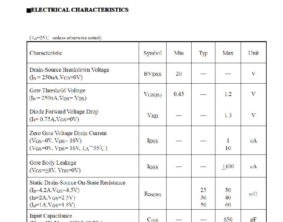
The only spec you need to be aware off for switching is the on-resistance table in the second of your links.
This lists the guaranteed on-resistances for several possible gate-source voltages, this is what you need
for using it as a switch. This device is definitely logic level, will work from 5V, 3.3V or even 1.8V logic.
You can check the datasheet screenshots here (the images don't load):
The critical detail missing from this discussion so far is the purpose of the circuit.
Is it to control something using PWM? If so, you need (though some dispute it) the 220 Ohm resistor in series with the gate of the FET because switching it on and off at a high speed is repeatedly charging and discharging the gate capacitance of the FET and will draw significant current from the Arduino pin which has a rating on the maximum safe current, so the resistor limits how much current is drawn.
If the load is only occasionally switched on and off - say, once per second - then there is probably no need for the series resistor.
The "pull-down" resistor is not actually needed when the FET is being driven by an Arduino pin except that when the Arduino is just booting up and until the code defines the pin controlling the FET as an OUTPUT, the gate will be floating at an indeterminate level. This means that the FET will be randomly switched on or off which may be undesirable for the load and if only partially switched on, may be dissipating a substantial amount of power which it would not if fully switched on, and could possibly be damaged.
Since the FET gate is a very high impedance at near DC, the resistor can be a very high value such as 22k or 47k and will be adequate for this purpose. As a point of design, since its actual purpose is to stabilise the Arduino pin until it is set to OUTPUT, the resistor goes from the Arduino pin to ground, before the series resistor, not at the FET gate.
antsor:
You can check the datasheet screenshots here (the images don't load):
Note that the static drain-source on state resistances are specified at logic levels, so this is a suitable logic-level device. At 1.8 V on the gate and drawing 4 Amps, the 60 milliohm resistance would result in a dissipation of just under 1 Watt, so driven by a 5 V Arduino and for a lesser current, heatsinking should not be a problem.
MarkT:
This lists the guaranteed on-resistances for several possible gate-source voltages, this is what you need
for using it as a switch. This device is definitely logic level, will work from 5V, 3.3V or even 1.8V logic.
Paul__B:
Note that the static drain-source on state resistances are specified at logic levels, so this is a suitable logic-level device. At 1.8 V on the gate and drawing 4 Amps, the 60 milliohm resistance would result in a dissipation of just under 1 Watt, so driven by a 5 V Arduino and for a lesser current, heatsinking should not be a problem.
This is what I'm not sure to understand. Why would I care about such a little resistance?
Paul__B:
The critical detail missing from this discussion so far is the purpose of the circuit.
In the circuit, a first MOSFET will control the power supply of a LED matrix (32*8 ) and the other MOSFETs will control LEDs that will blink up to 20 times per second. So I guess that in my case, I have to insert this 220 Ohm resistor?
Paul__B:
the resistor can be a very high value such as 22k or 47k and will be adequate for this purpose. the resistor goes from the Arduino pin to ground, before the series resistor, not at the FET gate.
Ok so in a nutshell, this schematic would be what I need for my circuit (reminder: the led theoretically represents my circuits) :
But I must tell you - "low-side" switching is inappropriate for a LED matrix that contains logic circuits that connect to your same circuitry as the pins controlling the matrix will be pulling down the matrix controller inputs even when you disconnect the ground - a very bad idea!
Time to fix the "XY Problem" - tell us what LED matrix this is and why you think you need to interrupt the power instead of simply blanking it? OK, if it is a NeoPixel matrix, then a 32 x 8 will have a quiescent current of 250 mA but you need to switch the 5 V supply not ground.
OK, so it is not a NeoPixel matrix because a 256 x 8 would draw 14 Amps!
As per my calculations in #11, even small resistances result in significant dissipation with large currents. The SL2300 is tiny and I would be concerned about it dissipating one watt.
Paul__B:
Time to fix the "XY Problem" - tell us what LED matrix this is and why you think you need to interrupt the power instead of simply blanking it?
Well, that's a good question haha! I don't know why I had this idea in mind but I've just realized that I actually didn't need to put a MOSFET to control the led matrix circuit. In fact, I only need MOSFETs for the other LEDs circuits.
Paul__B:
As per my calculations in #11, even small resistances result in significant dissipation with large currents. The SL2300 is tiny and I would be concerned about it dissipating one watt.
There won't be any significant power dissipations (tell me if I'm wrong) since I'll only have to use MOSFETs for LEDs connected in series and therefore, for a maximum current of 20mA.