Hi, this is my first post so please let me know if I am putting this in the wrong place or if I need to include more info.
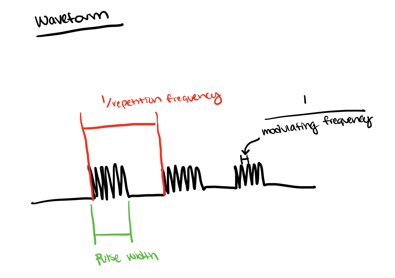
I'm trying to generate a waveform that looks like this, using a Mega 2560:
The image defines what I mean by repetition frequency and modulating frequency.
This is the code that I've tried to implement to generate the waveform:
#include <PWM.h>

  int stimulator = 9; //output pin

  int modfreq = 4000; //modulating frequency
  float modfreqtime = 1/modfreq; //convert to seconds so it can be used in delay to manually create frequency

  int repfreq = 99; //repetition frequency
  int pulsewidth = 50; //width of the repetition frequency pulse

void setup() {
    Serial.begin(115200);
    Serial.println(pulsewidth); //this is here because later I will be changing the pulse width and I want to have a way to check that I have the right value
}

void loop() {
  // generate waveform

    SetPinFrequencySafe(stimulator, repfreq); //set repetition frequency of pin
    analogWrite(stimulator, pulsewidth); //set pulse width
    delay(modfreqtime); //set modulation freq, could try to do this without delay

}
I tried to plot this in the serial plotter (by connecting the output pin (pin 9) on my board onto a separate board's analog pin (A9) and then reading that value) and am not getting the output I expected
This is the code I was using for the serial plotter:
It looks like it might be creating the repetitions at 99Hz, but I'm not sure how to get each repetition broken down into 10kHz.
Does anyone know if this is a problem with my code/the waveform that I am creating or if it is a problem with the serial plotter? And additionally, if there is a simple way to create the waveform that I want.
If I understood correctly you want to generate a burst signal that repeats. Is the burst waveform sine or just pulses? If its just pulses then in loop() you can generate pulses with on/off duration then write a LOW, delay for the long duration. Something like this:
void loop()
{
     //This for loop implements the burst of pulses
     for(int i = 0; i < numPulses; i++)
     {
             digitalWrite(PIN, HIGH);
             delayMicroseconds(pulseON);

             digitalWrite(PIN, LOW);
             delayMicroseconds(pulseOFF);
      }

      delay(BURST_OFF_TIME);
}
Hi,
Have you looked at the tone library to generate the 10KHz for a start, then write some code to gate the tone ON and OFF?
Here is an example code;
//A sketch to demonstrate the tone() function

//Specify digital pin on the Arduino that the positive lead of piezo buzzer is attached.
int piezoPin = 8;

void setup() {

}//close setup

void loop() {

  /*Tone needs 2 arguments, but can take three
    1) Pin#
    2) Frequency - this is in hertz (cycles per second) which determines the pitch of the noise made
    3) Duration - how long teh tone plays
  */
  tone(piezoPin, 1000, 500);

  //tone(piezoPin, 1000, 500);
  //delay(1000);

}
Yes output samples from a buffer. Make a buffer, an array, of one cycle of your required waveform. Then output this to a PWM pin with the PWM running at about 30 to 50 KHz. The resulting waveform will appear on the PWM pin. You could also have a timer generating an interrupt with the ISR simply transferring one sample to the PWM pin, and incrementing a pointer to the next sample.
You are not even restricted to square waves and 8 bit sample will be converted to a serial level.
P.S. you will never be able to see a very fast signal on the serial plotter, it is not like it is an oscilloscope.
1 and modfreq are both 'int' so 1/modfreq is done in 'int' and the result is zero. You probably want 1.0/modfreq to get 0.00025 (250 microseconds) instead of 0.