Hello everyone,
I'm trying to generate an AM signal with a carrier frequency of 20kHz using an Arduino UNO R3. I came across some sources on the internet and YouTube that suggested using the MCP4725 DAC module. However, I discovered that the MCP4725 can only generate signals up to 1kHz. Now, I'm wondering if I can use the AD9833 module to generate the AM signal instead.
Any help will be appreciated.
1 Like
Why did you start a topic in the Uncategorised category of the forum when its description is
![]() DO NOT CREATE TOPICS IN THIS CATEGORY
DO NOT CREATE TOPICS IN THIS CATEGORY ![]()
Your topic has been moved to the Project Guidance category
Well that is a programmable signal generator so it is not very suitable.
However, there is no need to use a DAC, you just use PWM, with a RC restoration signal. Make the PWM frequency higher than you need and then just change duty cycle of the PWM.
What is the frequency you want to modulate on this carrier?
consider using a DDS module - try a web search for arduino dds
Grumpy_Mike, thank you for investing your time and effort into this.
Based on your valuable suggestion, I understand that I can achieve the desired AM signal by utilizing an RC ladder and variable PWM, given that the modulating signal operates at a frequency of 50 Hz and the carrier signal operates at 20 kHz. Is my understanding correct?
Assuming my understanding is correct, I am faced with two options. 1- The first option involves using a look-up table, which may be complex due to the larg number of samples in the given table. 2- The second option is to utilize the AM modulation formula to generate the PWM value using for example the millis() function which is more logical in my work I think. Since I intend to implement the timer1 interrupt routine, I would appreciate your recommendation for the timer1 frequency.
It should be mentioned that, If I opt to use a timer1 routine frequency of 200 kHz, this implies that I would have approximately 10 samples for each cycle of the carrier signal (since 200/20 = 10). Would this resolution be considered adequate?
Thank you in advance for your support.
No, I never said or implied anything about RC ladder, I said RC filter. These are two different things. But otherwise this is correct.
Well given that you haven't said what this 50Hz modulation you want it is hard to say.
A look-up table is the fastest way to go. If you want to just calculate the size of the wave at any instant that implies you could calculate the modulation at any instant. The only problem is if this calculation can be done at a rate of less than 200,000 times a second.
You do know the legal implications of transmitting at 20KHz?
This will change from country to country but generally without you having a license to do this it is illegal.
Again for what?
The Nyquist rate is two samples per cycle of any wave to be able to recover information, and you propose to use 10 samples so this is 5 times the Nyquist rate, so you should be able to recover the modulated information.
Hi, @arja008
What is the application?
Why do you need a 20kHz carrier modulated at 50Hz?
Thanks.. Tom... ![]()
![]()
![]()
![]()
did you ever get the 20 kHz carrier modulated at 50Hz working?
using ESP32 with a AD9833 DDS module and a X9C103S Digital Potentiometer I get

zoom up to see the 20kHz carrier
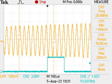
1. Is your carrier wave bi-polar sine wave or uni-polar square wave?
2. Is your modulating wave bi-polar or uni-polar?
original is a uni-polar sine wave, e.g. AD9833 DDS 20kHz signal (blue line is 0volts)

is fed to the X9C103S Digital Potentiometer via a capacitor to give a bi-polar input signal

the X9C103S Digital Potentiometer then modulates the 20kHz carrier at 50Hz
1 Like
Are you looking for an audio signal or an RF signal? The audio must have a wired connection. The RF signal needs antennas.
This topic was automatically closed 180 days after the last reply. New replies are no longer allowed.