For my final exams in school I am writing about data-transfer - especially about amplitude-modulated signals.
Now I run into troubles programming my Arduino...
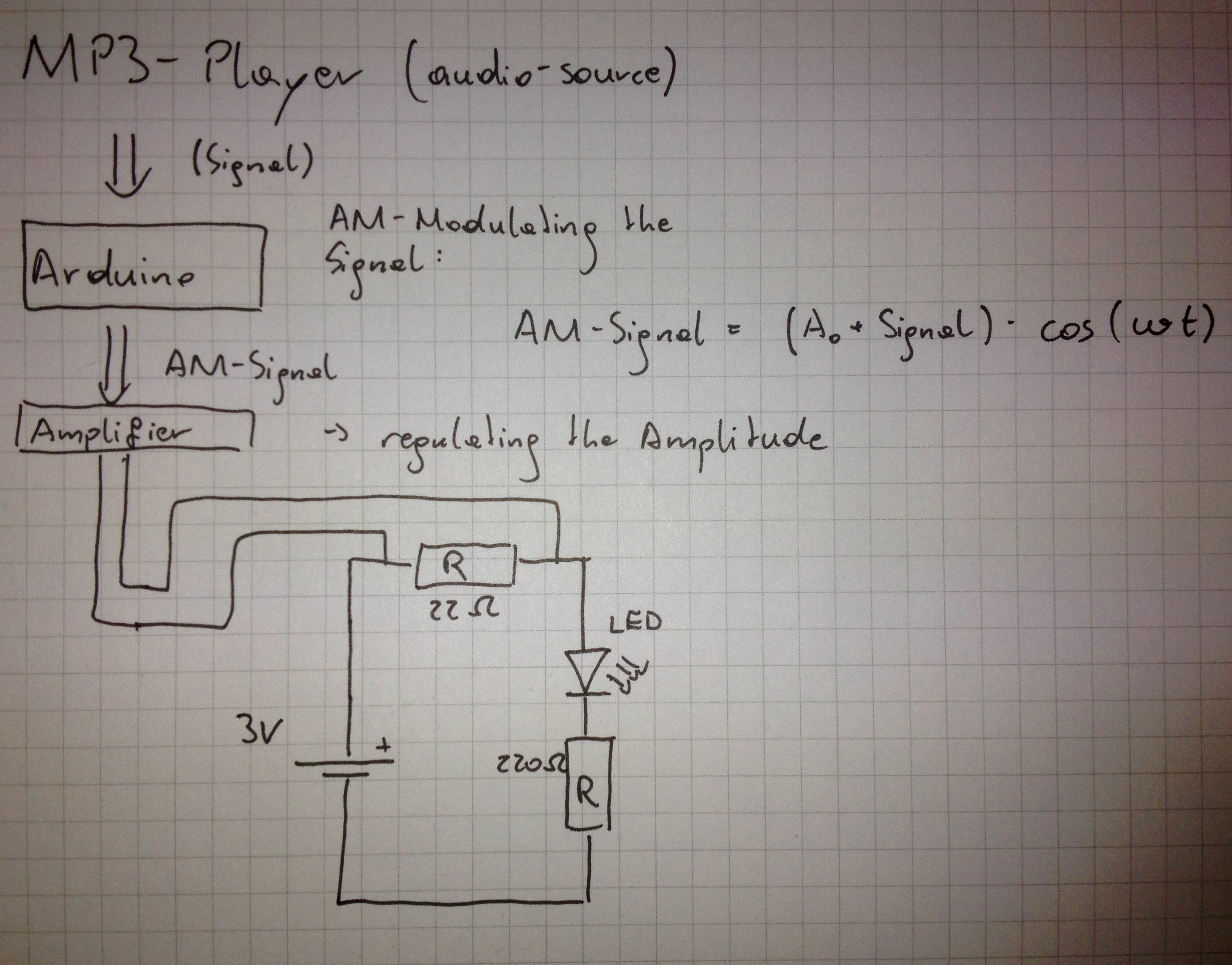
AM modulation is described with the formula:
AM=(A+Input)cos(xt)
AM ... Signal to send
A ... a constant number (the cos() can only be between -1 and 1; by having this "A" in the formula, the AM signal can't get 0)
Input ... is the Signal (unmodulated)
cos(x*t) ... the cos depending on the time; and "x" is a value, that regulates the ground frequency
I haven't used the Arduino for quiet a while and have tried everything I could think of to make this work, but it didn't work out.
I would really appreciate it, if anyone could help me with my problem
How do you propose amplitude modulation with a 0 or 5V output signal?
Best you can do is lowpass filter a PWM output to make it look ACish.
Or use an external DAC to create DC levels that you can control, from simple R-2R ladder to parallel/I2C/SPI interface DAC ICs.
And I just had a look at the Wiki article you linked me to, but I don't actually know how they achieve the modulation... But I Know for sure, that my formula works as well.
And you are right, the signal can can get 0. But what I meant was, that if there is no input signal, you still have an amplitude at the cos-function.
And to the things I have tried...
The goal of all of this is to have a song AM modulated - this AM-Signal should then be transferred over an LED to a solar panel there the signal gets demodulated again and you can listen to it.
By now, everything works, but not the AM-modulation.
And if the modulation would work, I could send multiple signals to the same solar cell and switch afterwards which information (song) I want to receive.
int Signal;
int A=2; //Wert
int t=0;
void setup(){
pinMode(4, OUTPUT);
}
void loop(){
analogWrite(4, AMSignal()); //Pin suchen
t++;
}
}
int AMSignal(){
int AM;
Signal=analogRead(5); //Pin suchen
AM=(A+Signal)cos(1000t);
return AM;
}
Thats the code I started with... I tried to use digitalRead and Write, analogRead and Write and PWM... but my programming skills are pretty bad (I even had help with this code).
And to check the result I am analyzing the signal with a oscilloscope... but until now i wasn't even able to change the base frequent (the cos() part)
CrossRoads:
How do you propose amplitude modulation with a 0 or 5V output signal?
Best you can do is lowpass filter a PWM output to make it look ACish.
Or use an external DAC to create DC levels that you can control, from simple R-2R ladder to parallel/I2C/SPI interface DAC ICs.
I wanted to try it with PWM.
And it doesn't matter, if the signal is DC, because I add a constant DC voltage anyway, to send the signal over an LED. Otherwise the LED would cut off the negative parts.
UKHeliBob:
Please post one or more of your attempts to code this for the Arduino.
Where does the input come from and where does the output go to ?
I have posted a sample of what I have tried in a previous post... (you commented while I was writing ;))
and the Input comes form an MP3 Player (the cable is modified so that I have 2 cables that I connect to the Arduino... I don't know where, but I thought that I should connect them to the Analog Input Pins.)
And the output goes to an amplifier that adapts the signal and applies it to the circuit with the LED.
Thanks for this code.
But something is odd... Somehow the formula is applied wrong. I don't know why, but this formula has to have constant frequency and a changing amplitude.
BUT right now, I have a signal generator as Input signal instead of the MP3 player... so I can set the frequency. But by changing the Frequency to the input signal, not the amplitude of the output signal is changed! the frequency os changed!
And that is mathematically incorrect.
@BerndR: My apologies. I have realized what your formula does - your explanation of it was confused and confusing (at least to my tiny mind). It does do amplitude modulation (under certain conditions) but not the way you've implemented it in your code.
If you constrain AM to be a number between -127 and 128, and add 127 so that the range is between 0 and 255, then you can output the result directly via analogWrite.
The OP has the correct formula for amplitude modulation, (A+signal)cos(ft), where signal is a function of time, but forgot the constant offset required for PWM.
In amplitude modulation there are two amplitudes, the constant carrier wave amplitude A and the modulating time variable amplitude represented by "signal". The time average of the modulated signal is zero.