I am new to arduino development and I am trying to generate two syncronized waves on two different pins using an Arduino UNO R4 WIFI:
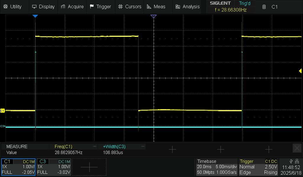
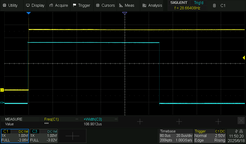
- square wave 30 Hz 50% duty cycle
- square pulse of 100µs synchronized on the rising edge of the square wave
I tried using delays and I was able to achieve the square wave, but not the pulse as it was not precise.
I am currently trying with two nested Fsp timers, but I am not able to make it work. Again, the square wave is correct, but the pulse does not occur every time it should.
Any type of guidance on the matter would be accepted.
Thank you in advance!
#include "FspTimer.h"

// Timer for the 30Hz square wave
FspTimer wave_timer;
uint64_t count = 0;
uint64_t start_time = 0;
int wave_pin = 5;
int wave_status = LOW;

// Timer for the 100us pulse
FspTimer pulse_timer;
int pulse_pin = 6; // New pin for the pulse output

// Callback method for the 30Hz square wave timer
void timer_callback(timer_callback_args_t __attribute((unused)) *p_args) {
  count++;
  if (!wave_status) {
    wave_status = HIGH;
    // On the rising edge of the 30Hz clock, start the pulse timer
    digitalWrite(pulse_pin, HIGH); // Set pulse pin HIGH
    pulse_timer.start();           // Start the pulse timer for 100us
  } else {
    wave_status = LOW;
  }
  digitalWrite(wave_pin, wave_status);
}

// Callback method for the 100us pulse timer
void pulse_timer_callback(timer_callback_args_t __attribute((unused)) *p_args) {
  digitalWrite(pulse_pin, LOW); // Set pulse pin LOW after 100us
  pulse_timer.stop();           // Stop the pulse timer
}

bool beginTimer(float rate) {
  pinMode(wave_pin, OUTPUT);
  pinMode(pulse_pin, OUTPUT); // Initialize pulse pin as output

  uint8_t timer_type = GPT_TIMER;
  int8_t tindex = FspTimer::get_available_timer(timer_type);
  if (tindex < 0) {
    tindex = FspTimer::get_available_timer(timer_type, true);
  }
  if (tindex < 0) {
    return false;
  }

  FspTimer::force_use_of_pwm_reserved_timer();

  // Setup the 30Hz audio timer
  if (!wave_timer.begin(TIMER_MODE_PERIODIC, timer_type, tindex, rate, 0.0f, timer_callback)) {
    return false;
  }

  if (!wave_timer.setup_overflow_irq()) {
    return false;
  }

  if (!wave_timer.open()) {
    return false;
  }

  if (!wave_timer.start()) {
    return false;
  }

  // Setup the 100us pulse timer
  // Get another available timer for the pulse
  int8_t pulse_tindex = FspTimer::get_available_timer(timer_type);
  if (pulse_tindex < 0) {
    pulse_tindex = FspTimer::get_available_timer(timer_type, true);
  }
  if (pulse_tindex < 0) {
    return false; // No available timer for pulse
  }

  // We want a 100us pulse, so the period is 0.0001 seconds.
  if (!pulse_timer.begin(TIMER_MODE_ONE_SHOT, timer_type, pulse_tindex, 10000.0f, 0.0f, pulse_timer_callback)) {
    return false;
  }

  if (!pulse_timer.setup_overflow_irq()) {
    return false;
  }

  if (!pulse_timer.open()) {
    return false;
  }

  // The pulse timer will be started in the audio_timer's callback
  return true;
}

void setup() {
  Serial.begin(115200);
  // Try to begin both timers
  if (!beginTimer(30)) {
    Serial.println("Failed to start timers!");
    while (1); // Halt if timers can't be started
  }
  start_time = millis();
  digitalWrite(pulse_pin, LOW); // Ensure pulse pin is low initially
}

void loop() {
  // calculate the effective frequency
  // This part of the code remains the same as it monitors the 30Hz clock
  int freq = 1000 * count / (millis() - start_time);
  Serial.println(freq);
  count = 0;
  start_time = millis();
  delay(1000);
}