Hi there,
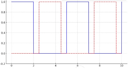
But The following code generates the following picture:
`void setup() {
  pinMode(9, OUTPUT);
  pinMode(10, OUTPUT);

  TCCR1A = (1 << COM1A1) | (1 << COM1B1) | (1 << COM1B0) | (1 << WGM11);
  TCCR1B = (1 << WGM13) | (1 << WGM12) | (1 << CS10);

  ICR1 = 79;

  OCR1A = 31;

  OCR1B = 47;
}

void loop() {
}
`
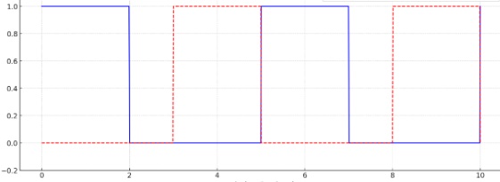
void setup() {
  // Set pin modes for Timer 1 output
  pinMode(9, OUTPUT);  // OC1A
  pinMode(10, OUTPUT); // OC1B

  // Set Timer 1 to Fast PWM mode, with a prescaler of 1
  TCCR1A = (1 << COM1A1) | (1 << WGM11) | (1 << COM1B1); // Clear on compare match, set at BOTTOM
  TCCR1B = (1 << WGM12) | (1 << WGM13) | (1 << CS10);     // Fast PWM, TOP = ICR1, no prescaler

  // Set frequency to 200 kHz
  ICR1 = 79; // F_CPU / (N * f) - 1; N=1, f=200kHz, F_CPU = 16MHz
  OCR1A = 32; // 40% duty cycle for first wave (0.4 * 80)
  OCR1B = 48; // 40% duty cycle for second wave (0.4 * 80) but start at 40 (80-40)
}

void loop() {
  // Main loop does nothing
}
Does this fix the issue?
I don't know how you would do that. You need to specify three points in the count - the end of the first wave, the beginning of the second, and the end of the second (which is not the end of the count). But you only have two registers. I think ICR only lets you specify the end of the count, but per your drawing you want the count to continue after the end of the second wave.
6v6gt
October 11, 2024, 2:27am
4
Isn't the net result of that a 400 kHz signal with an 80% duty cycle or am I missing something?
I don't think it is possible to do what you want with Timer1 on the ATmega328.
horace
October 11, 2024, 5:10am
6
you could try using simple loops, example using an ESP32
however, the microcontroller is dedicated to generating pulses and unable to do anything else, e.g. reading sensors
as @jremington stated generating the pulses using the UNO timer may not be possible
you could try using ESP32 timer interrupts
// ESP32 timer inteerrupts -   100KHz square wave print period counter

#define pin 19

hw_timer_t *timer = NULL;

// timer ISR invert pin level
volatile int counter = 0;
void ARDUINO_ISR_ATTR onTimer() {
  static uint32_t level = 0;
  counter++;
  // digitalWrite(pin, !digitalRead(pin));
  gpio_set_level((gpio_num_t)pin, level);  //!gpio_get_level((gpio_num_t)pin));
  level = !level;
}

void setup() {
  Serial.begin(115200);
  pinMode(pin, OUTPUT);
  timer = timerBegin(2000000);            // Set timer frequency Mhz
  timerAttachInterrupt(timer, &onTimer);  //  Attach onTimer function to our timer.
  // Set alarm to call onTimer function(value in microseconds).
  // Repeat the alarm (third parameter) with unlimited count = 0 (fourth parameter).
  timerAlarm(timer, 10, true, 0);
}

void loop() {
  // display counter every second
  static long timer1 = millis();
  if (millis() - timer1 > 1000) {
    timer1 = millis();
    Serial.println(counter);
    counter = 0;
  }
}
Use a Phase Correct PWM mode.
/**
  * URL: https://dbuezas.github.io/arduino-web-timers/#mcu=ATMEGA328P&timer=1&topValue=ICR1&ICR1=1740&timerMode=PCPWM&CompareOutputModeA=clear-up%2C+set-down&OCR1A=16&CompareOutputModeB=set-up%2C+clear-down&OCR1B=24
  * Mode     : PCPWM
  * Period   : 5 us
  * Frequency: 200 kHz
  * Outputs  :
  *  - B1: 40.00%, clear-up, set-down
  *  - B2: 40.00%, set-up, clear-down
  */
void setup(){
  noInterrupts();
  TCCR1A =
    1 << COM1A1 |
    1 << COM1B1 |
    1 << COM1B0 |
    1 << WGM11;
  TCCR1B =
    1 << WGM13 |
    1 << CS10;
  DDRB =
    1 << DDB1 |
    1 << DDB2;
  OCR1A = 16;
  OCR1B = 24;
  ICR1 = 40;
  interrupts();
}
The closer you bring OCR1A and OCR1B to 20, the more you get to 50% dutycycle and less deadzone for a H-Bridge driver you will have, assuming that's what you need this for.
e.g.
  OCR1A = 19;
  OCR1B = 21;
would give you a 47.5% dutycycle, but still without overlap.
2 Likes
horace
October 11, 2024, 2:33pm
10
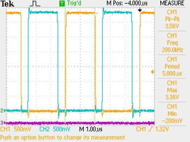
using ESP32S3 RMT
// ESP32S3 RMT two 200KHz pulses 40%duty cycle sync test
#include "Arduino.h"
#include "driver/rmt_tx.h"
void setup() {
Serial.begin(115200);
delay(2000);
Serial.println("ESP32S3 RMT two 200KHz pulses sync test");
delay(2000);
// setup Tx channels
rmt_channel_handle_t tx_channels[2] = { NULL };
gpio_num_t tx_gpio_number[2] = { GPIO_NUM_14, GPIO_NUM_15 }; // pin numbers
for (int i = 0; i < 2; i++) {
rmt_tx_channel_config_t tx_chan_config = {
.gpio_num = tx_gpio_number[i],
.clk_src = RMT_CLK_SRC_DEFAULT,
.resolution_hz = 10 * 1000 * 1000, // 10MHz clock
.mem_block_symbols = 64,
.trans_queue_depth = 1,
};
ESP_ERROR_CHECK(rmt_new_tx_channel(&tx_chan_config, &tx_channels[i]));
}
rmt_transmit_config_t transmitConfig = {
.loop_count = -1
};
rmt_encoder_handle_t copyEncoder{ NULL };
rmt_copy_encoder_config_t copyEncoderConfig = {};
assert(rmt_new_copy_encoder(©EncoderConfig, ©Encoder) == ESP_OK && "Failed to Create Copy Encoder");
ESP_ERROR_CHECK(rmt_enable(tx_channels[1]));
ESP_ERROR_CHECK(rmt_enable(tx_channels[0]));
// setup sync manage for the two pulses
rmt_sync_manager_handle_t synchro = NULL;
rmt_sync_manager_config_t synchro_config = {
.tx_channel_array = tx_channels,
.array_size = sizeof(tx_channels) / sizeof(tx_channels[0]),
};
ESP_ERROR_CHECK(rmt_new_sync_manager(&synchro_config, &synchro));
Serial.println("Starting Transmitters");
// setup pulse patterns - clock is 10MHz
// two 200KHz puilses 40% duty cycle
const rmt_symbol_word_t pulsePattern1[] = {
{ .duration0 = 20, .level0 = 1, .duration1 = 30, .level1 = 0 },
};
const rmt_symbol_word_t pulsePattern2[] = {
{ .duration0 = 25, .level0 = 0, .duration1 = 20, .level1 = 1 },
{ .duration0 = 5, .level0 = 0, .duration1 = 0, .level1 = 0 },
};
assert(rmt_transmit(tx_channels[0], copyEncoder, &pulsePattern1, sizeof(pulsePattern1), &transmitConfig) == ESP_OK && "Failed to begin transmitting");
assert(rmt_transmit(tx_channels[1], copyEncoder, &pulsePattern2, sizeof(pulsePattern2), &transmitConfig) == ESP_OK && "Failed to begin transmitting");
Serial.println("Transmitters Running");
}
void loop() {
}
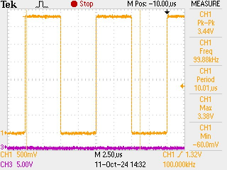
gives
checking pulse width
Thank you so much " [hmeijdam] Edison". It is the best solution.
system
April 9, 2025, 5:06pm
12
This topic was automatically closed 180 days after the last reply. New replies are no longer allowed.