aarg:
What is this "external source ground" that you speak of?
The Arduino ground and the relay board ground must be connected together.
No. If - and only if - the 5 V relay power supply is also being used to power the Arduino, then separately to the 5 V and ground wires from the power supply to relay board, you would run 5 V and ground wires from the power supply to the Arduino.
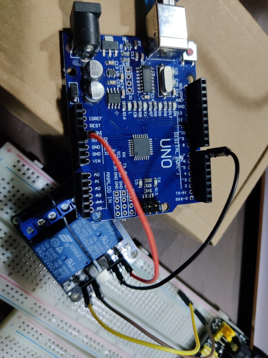
If the onboard relay LED is blinking, and the relay is not operating, your problem is on the relay driver side of the optocoupler. Check for 5V 12V power on JDVcc/GND. You have 12V relays (see the photos). 5V will not operate them reliably, if at all.
mmitchellmoss:
Need a common ground between Arduino and external power supply?
No.
The opto LED is connected between VCC and IN1/2.
Ground of the relay board should NOT be connected to Arduino ground.
You can, but then you loose opto isolation.
PaulS:
pinMode(in1, OUTPUT);
Does that look strange to anyone else?
Confusing name, but code seems ok.
int in1 = 7;
If the indicator light goes on/off, but you don't hear the relay click, then it could be the 9volt smoke alarm battery.
Relays like this draw about 75mA coil current each, and your 9volt smoke alarm battery might not be able to provide that when it's not fresh.
void setup() should look like this to prevent relay chatter during boot-up.
aarg:
If the onboard relay LED is blinking, and the relay is not operating, your problem is on the relay driver side of the optocoupler. Check for 5V 12V power on JDVcc/GND. You have 12V relays (see the photos). 5V will not operate them reliably, if at all.
Yuhu!
9V to the relays instead of 12V was indeed the issue!
Trying to get something in before work here, didn't have time to go through the motions - I mean, the photos!
From the top: Pseudo-UNO (actually a SMD Duemilanove clone) is fine.
12 V relay module wired absolutely correctly, but needs 12 V as the relay supply. Quite possibly would work on 9 V and might even work on that battery if it is alkaline and only one relay actuated.
"Breadboard" power supply is generally pretty useless due to its limited heatsinking of the regulator(s). Would probably manage to power one 5V relay only. But in any case, relays should be operated at their specified voltage from a power supply designed for that voltage (which may include a battery - a 6 V battery is fine for driving 5 V relays).
"PP3" battery - AKA "smoke alarm battery" is of extremely limited use in powering Arduino projects due to its low current provision capacity (it consists of six "AAAA" cells) and limited mAH overall capacity. Alkaline versions might last a little while.