Hello,
I currently received a relay module and I am learning how to use it but it doesnt work. My arduino nano is powered with usb cable and the vcc is powering the relay and Arduino nano ground is connected to relay ground. However, when I test to see if the circuit works, the green light turns on but the output shows no connection. The code should not be the problem. I have a bluetooth device connected that I for sure know works that tells the relay to turn on and off. Anyway, the pin for the relay is supposed to turn on HIGH when button is pressed. When it does, the green light turns on but no connection is made.
I am trying to use a relay with an Arduino Nano. I have set it up multiple ways with no luck. The first way I tested with my computer a simple relay sketch and the led on the relay flashed when it was supposed to but it never clicked which means it wasn't working. The next idea I used a 10.3v power supply and hooked it up to the Arduino nano and relay module and both lights turned on for the relay and it clicked but would ever change. Any Ideas?
Thank you.
Code -
int relayPin = 13;                 // LED connected to digital pin 13

void setup()
{
  pinMode(relayPin, OUTPUT);      // sets the digital pin as output
}

void loop()
{
  digitalWrite(relayPin, LOW);   // sets the LED on
  delay(2000);                  // waits for a second
  digitalWrite(relayPin, HIGH);    // sets the LED off
  delay(2000);                  // waits for a second
}
I'd say you should provide details of / link to the "relay module" (which come in various forms from what I've seen), along with a schematic of how you've wired it up.
... mean it sounded like it was switching but wasn't actually? How're you checking that it's not switching?- do you have a load on the relay output, or checking continuity with a dmm, or what?
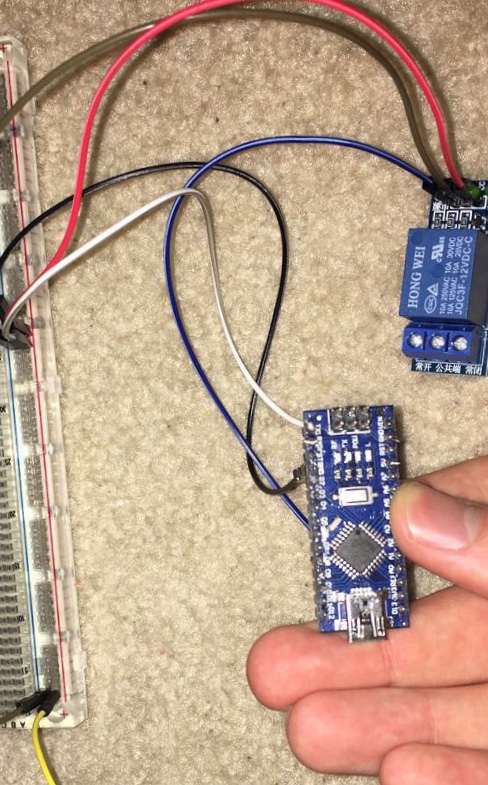
Sorry for the horrible question. I am checking with a multimeter. This is the eBay link I bought it from, however, the letters at the bottom spell "JQC3F-12VDC-C". When I plugged it in the second time I tested it, the relay turned on and clicked but would stay on no matter what.
Seems to me that "JQC3F-12VDC-C" indicates it needs 12V on the coil to switch yet your link is to a 5V one.
I'm not sure how it would (could?) wire to an Arduino, if it looks like the link but is actually 12V.
Does it look like the pic in the link, save for being 12V? Or is it actually a different design, perhaps with a JD-Vcc connector which would allow for 5V control yet 12V power to the coil?
Maybe post a photo of the actual one, to see its layout and markings, and your wiring?
Can you confirm if the relay blue block itself is 5V or 12V?
If 12V, I "suppose" it could switch with 10V; if 5V then 10V is too much. Was that "JQC3F-12VDC-C" you uoted, from the actual blue block (can't read the markings in the photo)?
Maybe just for the hell of it, try a different pin from 13 which has the built in LED on it.
A hand drawn sketch of the circuit might help to clarify the circuit.
oKeeg:
The blue block does say 12v.. does that mean I bought the wrong one then or is it still compatible?
I've never used one, so not 100% sure.
It would need a nominal 12V on the coil to switch reliably, that's the Vcc and Gnd on the module.
The control line to IN is active low, so I reckon as long as the nano has common ground with the relay module, the nano's "low" on IN would activate it. But (and here I'm not sure, I may be talking crap) the nanao's 5V high may not be enough to de-activate it, which I think is what you said is happening?
To test the relay module by itself, take the nano out of play. Just with the 10V (or better yet, 12V out at your car....) on the relay module, take an extra -ve from the battery to the IN pin and on it and off it by touching that wire and removing it.