Hey all!
I'm doing a small project where I'm trying to connect my Arduino to a Roomba (iRobot Roomba 521) and get data from the front bumper sensors. I have found out that they work via a IR emitter and receiver. The default state of them (not hit an object) is where the IR light can pass to the receiver but when the Roomba hits an object, the bumper activates and blocks the light.
My goal is to feed the data into the Arduino so I can detect if it has collided with an object but I'm very much a beginner with electronics/Arduinos.
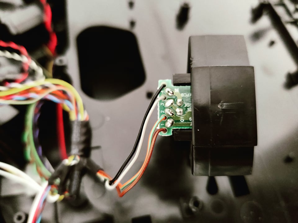
Here is a view of the small board holding the IR Rx/Tx:
Am I right in thinking that if I wanted to get data into the Arduino I would need to connect the IR receiver to an input pin on the Arduino? Based on the component listed on that page https://www.schneordesign.com/sdwp/wp-content/uploads/2018/07/LiteON_S_110_E302-346938.pdf I'm also guessing that the soldered wire on the top of the board is the anode and the pin below it is the cathode (the RX is the top two wires). Would I need to solder a wire onto both anode and cathode to input into the Arduino or just the cathode?
Also I read in a few places about common ground, do I need to connect the Roomba's ground to the Arduino's?
I hope all of this makes sense as I feel I'm even confusing myself at this point . If you need any more information or images of the setup just let me know!
well you should describe what you want to do in the end.
If you have almost no knowledge about electronics it will be difficult.
You haven't told if your roomba should go on working as usual.
I assume yes. So adding electronics should not disturb the existing electronics.
One way of making sure this is to use an OpAmp configured as a voltage follower
to minimise the impact of the additional circuitry on the existing circuitry.
I guess this is the first time your read the words "OpAmp" and "voltage-follower"
So next thing is to describe what you want to do in the end.
It might be that all of his is an XY-Problem.
best regards Stefan
Hey Stefan!
My end goal is to wire up a speaker system to the Roomba that can play from an SD card when the Roomba hits an object. I have the speaker side of things all done but I just need to interface with the Roomba's bumper sensor. I don't need the Roomba to clean so I have removed all the modules that relate to that. I am housing the electronics in the brush compartment on the underside of the Roomba where there is plenty of room for the Arduino, speakers and anything else I should need. I made holes where I can path the wires from the bumper sensors to the compartmeht where the Arduino will be so that's all fine. The last part is where I'm having some confusion, getting the IR setup in the bumper sensor to feed data to the Arduino so I can detect collisions. From the link I showed it looks like it's just a two pin IR emitter + receiver. My thoughts are that I can connect the IR receiver output straight to a pin on the Arduino and read the data coming from it. As the IR light is allowed to pass through the bumper by default and when a collision occurs the light is blocked by the mechanical bumper arm (circled in the picture above) I was wondering if I can just connect the cathode side of the IR receiver to the Arduino and read the data from it.
The Arduino's and Roomba's circuits will be completely separate apart from this single wire coming from the Roomba's IR receiver to get the data from it. Both powered separately for now.
I was mainly not sure if I can use use the one wire from the cathode side of the IR receiver into the Arduino to read the data or if I would need two wires from anode and cathode side.
I was also unsure about along side that wire, if I would link the ground between the Arduino and Roomba? Not sure if I was just misunderstanding "common ground". I read this:
A common mistake for people new to electronics is to have 2 circuits fed from different power supplies with signals passing between the circuits, but with the grounds not connected.
Yes it is my first time hearing about "OpAmp" and "voltage-follower", I will look into these
So this means the Roomba is driving around like cleaning but is no longer cleaning but instead playback MP3-files from SD-card when bumbing?
To connect two different electronics to exchange signals electrically the ground of both must be connected. The circuitry of the IR-receiver is unknown. There are very different ways how a IR-receiver can be connected to the rest of the electronic and the IR-receiver can be of different types a foto-diode or a foto-transistor (subtypes NPN or PNP) so it is a must to analyse what are the voltage-levels if the bumber is free or "bumbed-in". An OP-Amp-voltage-follower has almost no impact on the rest of the circuitry (except the IR-receiver is a foto-diode connected to an Op-circuitry called "trans-impedance-changer".
So do you have a digital multimeter to measure the voltage-levels?
If not this is the time to buy one. Without a digital mutlimeter you will have a very hard time to analyse anthing.
You have to switch on your roomba simulate it is driving.
Freewheeling with wheeles off the ground and then measure the voltage always between ground (minus of the battery and one wire of the IR-receiver. with sensor free and sensr "bumbed-in"
My Roomba stops when lifted from the floor. There is some sensor that must be fooled first.
@OP:
Wires 3 and 4 of the small board are important for you. 4 is probably GND but you should check it using a DMM or analogRead of Arduino (use a current limiting resistor about 10k if using Arduino as DMM). While doing so you can estimate voltage on the output of the phototransistor. It is possible there is some modulation - in that case values obtained may be difficult to interpret without an oscilloscope.
I would try a piece of wood with holes for the wheels and some small pieces that keep the chassis of the roomba at the same distance as the wheels would do when standing on his wheels.
best regards Stefan
The wheels have a spring with a sensor on them to tell when they are off the ground, if you push the wheels in slightly you will hear a click, that will disable that sensor (I just stuffed some tissue in there). Secondly there is the 4 IR sensors around the front of the Roomba that detect distance from the ground (edge sensors), to disable them just tape some white paper to each sensor so that it reflects the IR light and tricks the Roomba into thinking it's on the ground. Then you can get it to work while off the floor
Yea I think 3 and 4 are what I need as they are the receiver, based on IR receiver it looks like pin 4 is the anode and pin 3 the cathode. I have tested with a multimeter the left bumper pin 3 and I get around 109mv with bumper not pressed and 4.8v with it pressed.... I think maybe I have found out how do this . Time to wire up the right bumper pin 3 to see if I get the same result!
I also attached a wire to ground onto the Roomba and can attach that to the Arduino's ground so I have common ground between the two boards.
This should mean I can use digitalRead(pin) to get the high/low state of the bumper in the Arduino, right?
Edit:
Yep, just tested the right bumper and I'm getting the same result! It goes from 0.11v when the bumper isn't pressed to 4.93v pressed. Both sides giving the same result!
Edit 2:
Just tested out how the rest of the electronics will fit into the Arduino, it couldn't be a more perfect fit with not even 1mm room to spare on each side. I will get a second 9v battery to power the Arduino since the one in there will be powering the amplifier.
All that's left to do is wire it up and add some code for the digitalRead(pin) to trigger the audio.
I'm guessing I still need to add the 10k resistor for limiting the current (on the left/right bumper signal input wire)?