Hello Dear Forum,
my wish: getting notification on my Phone, when someone rings my Doorbell, plus a button via the Arduino Cloud to open the door. (atm I have a Arduino Nano IOT, I hope this can handle this project, it runs on 3.3V)
(maybe if im successfull in the future I could upgrade the system to be able to talk over the phone to the person ringing downstairs)
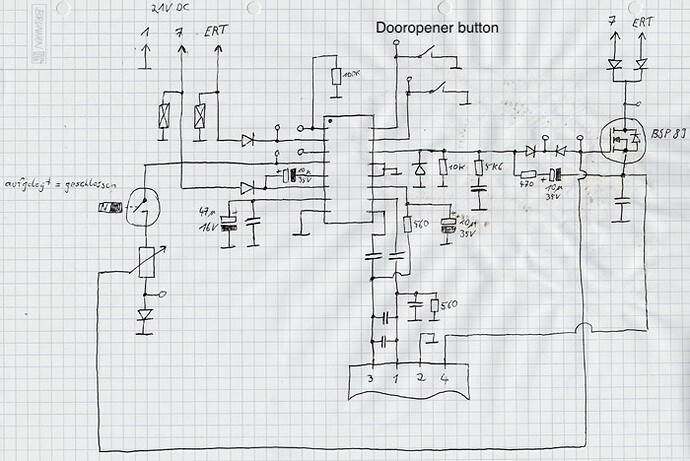
My Doorbell is from siedle and someone on the internet broke down pretty much the whole thing over here
To my knowledge I get 18V DC from the pin 7 and if someone rings the bell there is a voltage drop, which I could read with an optocoupler and a zehnerdiode (pls correct me if im wrong)
now I don't think I need help programming the Arduino, but I lack knowledge in the electronics world, so this is me asking help for the electronic part of the project, but of course if you have coding ideas feel free to share them though hopefully that should be the easy part of my project.
Now the next step is to be able to open the door with my Arduino, but im super confused about the whole button thing. I thought I could simulate the Button press with a relay or a (NPN) transistor but so far all my tries with a SSR or a Transistor have failed.
I think I measured a voltage of 6.25V, when I connected my multimeter to the two sides of the button, not sure if that helps.
Now I think I don't need to know how exactly a relay/transistor works, since I think I understand the base principle, but since I can't get it to work, I think I either need a full understanding of the things, or I need someone to tell me exactly how I need to connect the Arduino to the button to simulate it. I'm happy as long as it works, I don't need to understand it.
now the second big question is, can I power my Arduino from the Doorbell or do I need an external power source?(sadly I don't have a wall socket near the bell so it would be a hassle to somehow get the power from a socket )
Kind Regards Samelmann
