I know so little. It's hard for me to contribute anything to offset the help I get. And this post will only benefit someone on my level. Disclaimer complete.
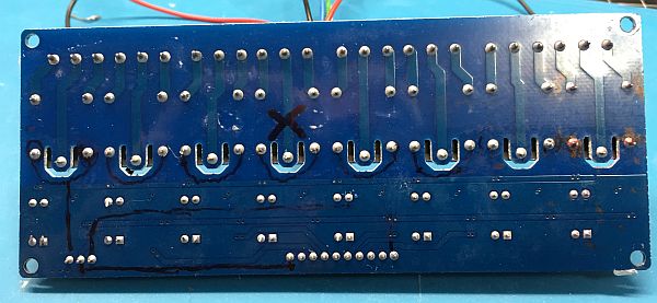
I notice a lot of questions about these relay modules (see pics). I've got one myself that's crapped out. But I'm convinced enough that it's blown that I'm not even going to ask for help. Just reordered instead.
But there is one tiny bit of trouble shooting that one might use to determine if the relay itself is trashed, or of it's in the PCB and all of those super tiny traces and components that would be next to impossible to repair.
I will mention that mine was working just fine before I left it on overnight for some testing. I noticed this morning that the LEDs were no long lighting and the relays no longer respond to signals from my breadboard. From what I can gather, it may have been damaged by low voltage. I inadvertently powered it with 3.3v instead of 5v.
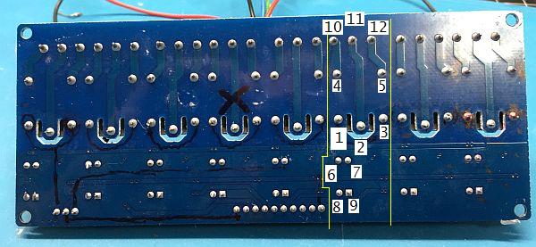
If you flip your board over so that it's oriented as shown in my picture, you can apply voltage to the pairs of pins I have marked (all 8 pairs). If the relays are functional, you'll here them click. You may still be out of business, but you can answer the question-- Do your relays click?
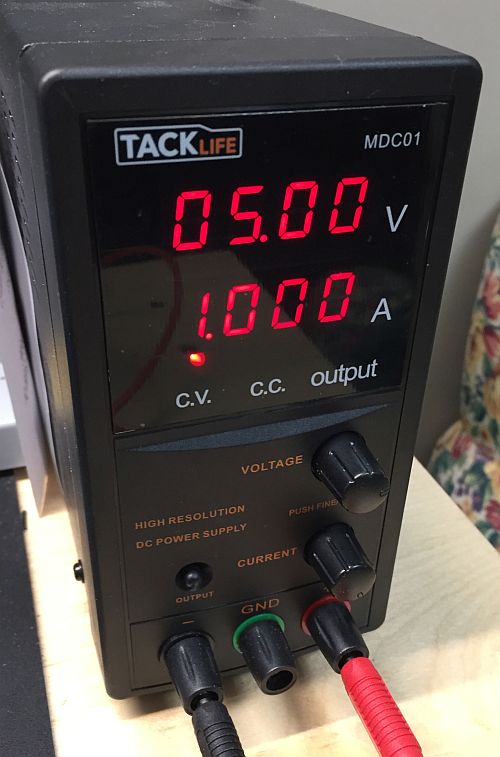
I used a 5v bench power supply with a current limit of 1 amp. The good relays drew about 72mA. The bad ones would peg the 1amp limit and my leads got hot. If you don't have a power supply, you can use some other 5v source. And since you can't control the current (the 1 amp limit I mentioned) you'll know the relay's shorted by the smoke (and no click). No click, no smoke = open-type failure.
But know this: I went through the whole board five or six times, marking the ones that worked and the ones that didn't. On subsequent checks, the bad ones checked good. So, you'll get some false results. I don't know if that speaks to the Chinese quality, or maybe I have some that are on the fence. The one with the black X consistently checks short.
I wish I had that schematic while I was poking around. I expect most of these devices to have no schematic other than on a napkin somewhere. But, I have it now, and will return to the bench. Thank you sir!
By the way-- How are you getting images to appear on screen rather than the attachment icon (paper-clip)? This is the only forum where I have that problem.
To post an image:
Right click on one, and Copy Image Address.
Go back to your post, select More, then Modify.
Type in [ img ] paste your link [ /img ] (without the spaces)
"You did power the coils with the correct polarity."
No. I took no concern for polarity as I had no way of knowing which polarity would be correct. My understanding (and you can correct me if I'm wrong), is that DC probing generally doesn't matter unless there's a diode. And I knew of no such diode (or much else).
I can't tell by the schematic which solder joints would be the probe points for D2. Apparently, my previous probing was 4 and 5. So I got in diode mode and checked them both ways. The unit with the black X was a dead short. All others were 0.037v in either direction. Uhh.. what's that all about? Thank you
Can you tell me which points would be for checking D2? Thank you. Note: My number tags are just random, no correlation to the numbers on the schematic.
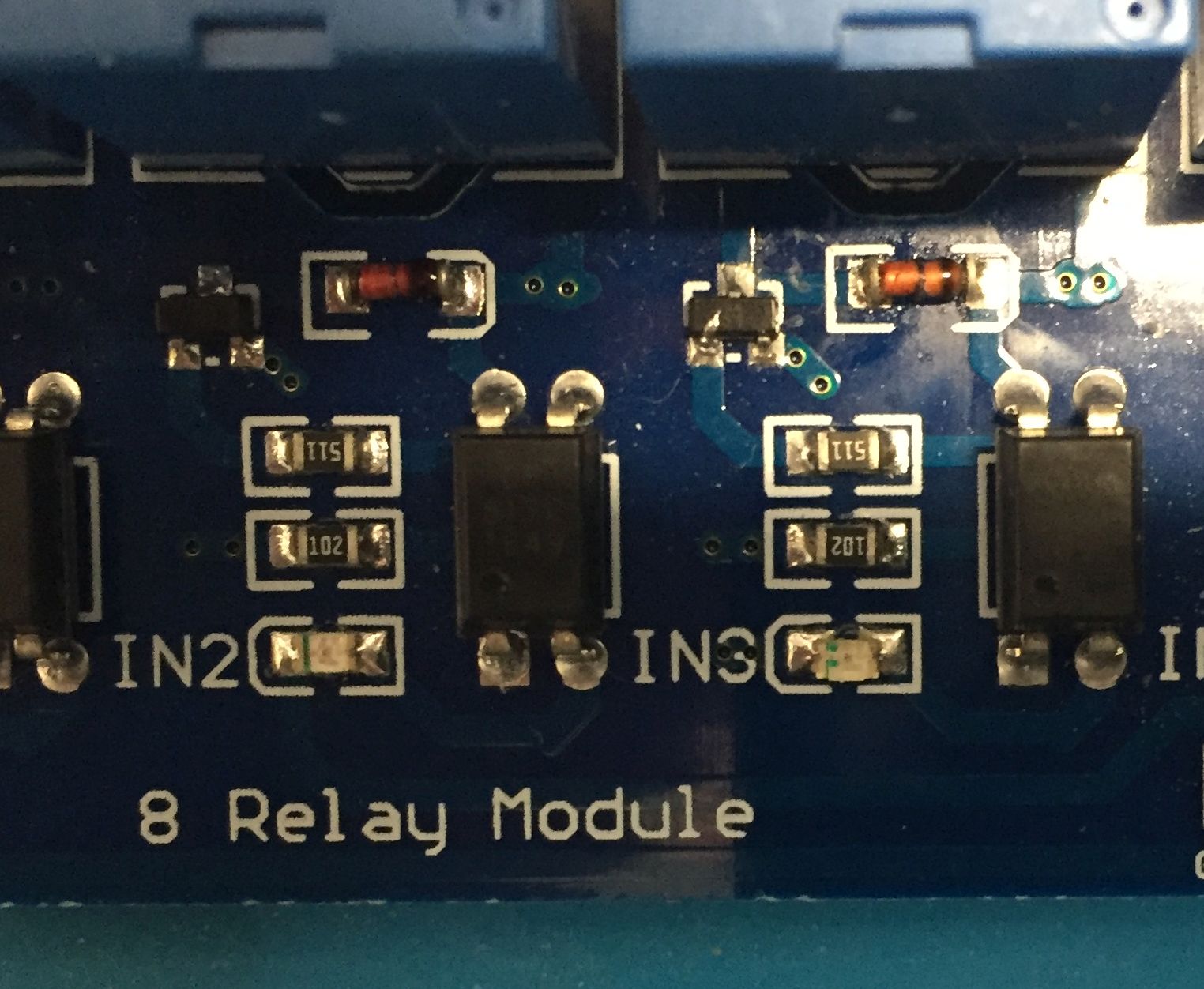
Need to see a better view of the I.C. section of the board.
Can you show us a better top view of this image?
Do your relays have a 70Ω coil?
The diode is hidden in this image, it will be a SMD package.
You can easily damage low amperage diodes if you forward bias them with 1 amp.
Your leads did get hot .
Thanks to a Robert Bacon video, I learned that I was connecting my relays incorrectly. To my great surprise, they work perfectly when following his instructions. Oddly (very oddly), the unit that shows dead short on probing, also works (clicks). But I'm learning a lot from this interchange with you and want to see it through. Maybe this can be a reference thread for others. Adding the Bacon link, photos coming shortly.
All the other folks did the heavy lifting (so to speak) but one line you wrote concerns me.
"You did power the coils with the correct polarity."
No. I took no concern for polarity as I had no way of knowing which polarity would be correct. My understanding (and you can correct me if I'm wrong), is that DC probing generally doesn't matter unless there's a diode. And I knew of no such diode (or much else).
If I understand you correctly your description of "DC Probing" is to connect the power supply and read the resulting current. If true.......
You may have learned in this case your assumption is incorrect, however you must get this thought out of your head. It is absolutely wrong.
DC circuits are designed expecting power to be the proper polarity. Many devices will be damaged by reversing voltages.
Most Semiconducors
Electrolytic capacitors
Tantalum capacitors
LEDs (well these are really diodes).
etc
"If I understand you correctly your description of "DC Probing" is to connect the power supply and read the resulting current. If true......."
When I speak of probing, I mean touching solder joints with my meter and/or my bench power source. I knew I was taking a chance it applying DC voltage to the solder joints as some circuits cannot tolerate reverse polarity. On the other hand, I was poking around in an effort to learn something from a piece I had removed from the trash can. At the risk of damaging something, maybe I would hear a click or see an indicator LED light up. Maybe it could be salvaged after all.
Lucky for me, the 8x relay board turns out to be fully functional despite my rookie trouble shooting. It was just wired up wrong. But I do take your point, believe me. If I was a technician working on an MRI machine, I wouldn't touch anything (with voltage) without knowing what I was poking. And, yes, I do know that even continuity checks involve some voltage.
I can't actually remember how I had it wired then, that's different from how I have it now. I just know that one day it was working, the next day it wasn't. At my age, it's very likely that I made a change that caused it to malfunction and didn't realize I was doing it. Or-- it might have even been my code. Part of what I learned in the Bacon video is the "forced high" technique in setup. So maybe the lack of that had something to do with it. Anyhow, here's how I have it now with notes to myself if I need them for reference next time. I hope the PNG file isn't too big. If it is, I'll redraw it. Hopefully this thread will be a suppository for future noobs failing to get their eight-packs working right. Seems like we've pretty well covered all the possibilities. Thanks to everyone.