I've been trying to connect my GPS module to my nano IOT for some time now but am not sure how because the Software Serial library does not exist. I don't know what code to use if I use TX RX connection.
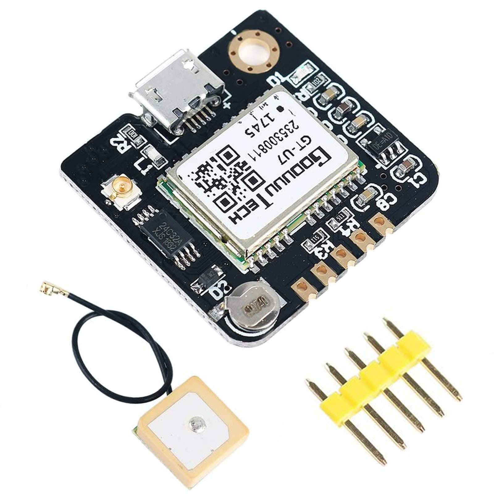
This is is the gps module im using:
Does it have a datasheet?
Also, post the source code in code tags, and a picture of a hand-drawn wiring diagram.
You don't need to use SoftwareSerial because the Nano 33 IOT has more than one hardware serial interface. Connect the GPS to pins 0 and 1 of the Nano and use Serial1 to communicate with it
The Serial port does not use pins 0 and 1 and it communicates directly with the PC so Serial and Serial1 do not interfere with one another
Note that as its name suggests, the Nano 33 IOT operates at 3.3V rather than 5V. It may not, therefore, be compatible with the GPS. Do you have the specification for the GPS ?
Do you have any sample code I could use? As for the GPS, we can try and send only 3.3 V to it and that will likely fix this 5V issue?
the RX on the module goes to TX on the Arduino. The TX on the module goes to the RX on the Arduino. you don't want to be the first person to ever make that mistake
int gpsBaudRate = 9600;  //set this to suit your GPS module

void setup()
{
    Serial.begin(115200);
    Serial1.begin(gpsBaudRate);
}

void loop()
{
    if (Serial1.available())  //if data available from GPS
    {
        Serial.write(Serial1.read());  //print it to the Serial monitor
    }
}
I have that same module. My memory is that it requires 5V power, which is then reduced to 3.3V by the LDO on the module (the little 5-pin chip). So its Tx output is 3.3V. That works well enough with a 5V Arduino. But I've never needed to connect the Rx line. It would be expecting 3.3V input, but the 5V Arduino would be sending data at 5V. So that might be a translation problem if you need to send stuff to the module.
But on the Nano 33 IOT, I think USB 5V connects to the Vin pin through a schottky diode, so Vin should provide 4.7V power, which you can use to power the GPS module. And then data is 3.3V both ways.
But if all you have is 3.3V power, one solution might be to short the LDO's input to its output. That would effectively bypass the LDO, so the incoming 3.3V would go directly to the rest of the circuit. It appears to be this LDO:
If the GPS module requires 5V power and you want to get the power from the 5V pin on the Nano 33 then you need to short the two solder pads on the bottom of the board adjacent to that pin. Doing this connects the 5V from USB to the 5V pin
Thank you everyone for your help! We figured out how to get the GPS working because we only supplied 3V to the breadboard for the GPS. It shouldnt send 5V signals