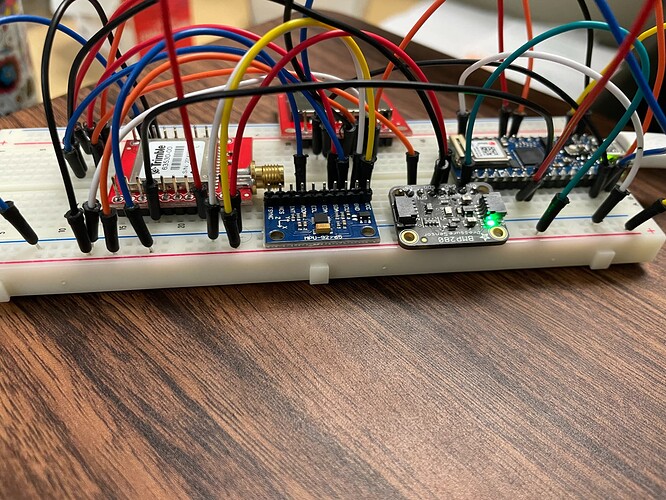
Hello, I am working on a tracking system and one of the modules is the Trimble Copernicus II GPS. The other sensors, MPU92/65 and BMP280 work fine when connected to the Arduino nano iot 33 but the Trimble Copernicus II GPS sensor isnt working.
The pin connection is as follows:
GPS VCC ---> Nano 3.3 V,
GPS GND ---> Nano GND,
GPS TX-B ---> Nano RX and
GPS RX-B ---> Nano Tx pin
I have tried this code
byte aa;
void setup()
{
  Serial.begin(4800);
  Serial.println("It works, so far");
}

void loop()
{
  if (Serial.available()>0) // if there is data coming into the serial line
  {
    aa = Serial.read(); // get the byte of data
    Serial.print(byte(aa)); // send it to the serial monitor
  }
}
No readings whatsoever
and also
#include <TinyGPSPlus.h>
#include <SoftwareSerial.h>
/*
   This sample sketch demonstrates the normal use of a TinyGPSPlus (TinyGPSPlus) object.
   It requires the use of SoftwareSerial, and assumes that you have a
   4800-baud serial GPS device hooked up on pins 4(rx) and 3(tx).
*/
static const int RXPin = 1, TXPin = 0;
static const uint32_t GPSBaud = 4800;

// The TinyGPSPlus object
TinyGPSPlus gps;

// The serial connection to the GPS device
SoftwareSerial ss(RXPin, TXPin);

void setup()
{
  Serial.begin(115200);
  ss.begin(GPSBaud);

  Serial.println(F("DeviceExample.ino"));
  Serial.println(F("A simple demonstration of TinyGPSPlus with an attached GPS module"));
  Serial.print(F("Testing TinyGPSPlus library v. ")); Serial.println(TinyGPSPlus::libraryVersion());
  Serial.println(F("by Mikal Hart"));
  Serial.println();
}

void loop()
{
  // This sketch displays information every time a new sentence is correctly encoded.
  while (ss.available() > 0)
    if (gps.encode(ss.read()))
      displayInfo();

  if (millis() > 5000 && gps.charsProcessed() < 10)
  {
    Serial.println(F("No GPS detected: check wiring."));
    while(true);
  }
}

void displayInfo()
{
  Serial.print(F("Location: "));
  if (gps.location.isValid())
  {
    Serial.print(gps.location.lat(), 6);
    Serial.print(F(","));
    Serial.print(gps.location.lng(), 6);
  }
  else
  {
    Serial.print(F("INVALID"));
  }

  Serial.print(F("  Date/Time: "));
  if (gps.date.isValid())
  {
    Serial.print(gps.date.month());
    Serial.print(F("/"));
    Serial.print(gps.date.day());
    Serial.print(F("/"));
    Serial.print(gps.date.year());
  }
  else
  {
    Serial.print(F("INVALID"));
  }

  Serial.print(F(" "));
  if (gps.time.isValid())
  {
    if (gps.time.hour() < 10) Serial.print(F("0"));
    Serial.print(gps.time.hour());
    Serial.print(F(":"));
    if (gps.time.minute() < 10) Serial.print(F("0"));
    Serial.print(gps.time.minute());
    Serial.print(F(":"));
    if (gps.time.second() < 10) Serial.print(F("0"));
    Serial.print(gps.time.second());
    Serial.print(F("."));
    if (gps.time.centisecond() < 10) Serial.print(F("0"));
    Serial.print(gps.time.centisecond());
  }
  else
  {
    Serial.print(F("INVALID"));
  }

  Serial.println();
}
I get Error compiling for board Arduino NANO 33 IoT. Is my pin connection the issue or what exactly am I missing?
Any help will be much appreciated.
