That's impressive. But you say you are a beginner. Is it just Arduino you are new at?
Pedantic point: You can totally hot-disconnect a GNSS receiver antenna since it's just a receiver. It's transmitters that 100% require an attached antenna when powered.
Thanks for that. So the antenna itself doesn't mind being suddenly powered or de-powered.
I should have explained my reasoning. When handling the tiny uFl connector it is very easy to create a short across the inner and outer connectors of the receptacle. When that happens you'll see the GPS on-board LED go out. U-blox emphasise the sensitivity of the RF circuits.
I don't know if the short really does cause damage but it seems good practice to avoid doing it. Is that sensible?
I have dead antennas and I'm happy to accept it's probably my poor handling practices that is the cause.
1 Like
Hi,
What is your power supply, what is Vin volts?
Tom.. ![]()
![]()
![]()
![]()
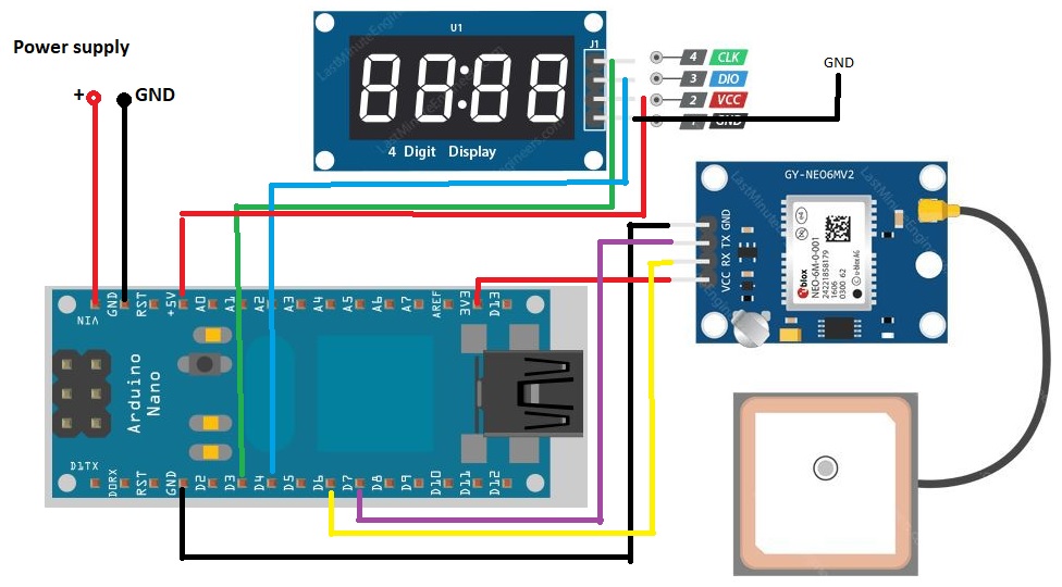
If pin 6 is the Nano Rx it should be connected to the NEO Tx.
If pin 7 is the Nano Tx it should be connected to the NEO Rx.
Check your wiring and Fritzy picture.
Its a UART comms thing...
Tom.. ![]()
![]()
![]()
![]()
![]()
TomGeorge has it.
You can supply the board with 5v. It has a regulator that provides 3v to the neo 6m.
Hi, Its 12V
So the RX must be connected to the TX?
That tool on the image - is the STL file available somewhere?
Here. Is very simple...
1 Like
Thanks a lot ![]()
Yes...
Tx is data out.
Rx is data in.
Tom.... ![]()
![]()
![]()
![]()
1 Like
Thank you
My sketch I added in the first post is right?
Note: About 1% of the time the person who labels the pins gets them swapped. If your serial communication isn't working, one thing to try before you declare your hardware 'broken' is to swap the wires. ![]()
Friday news. I replaced the defectively assembled GPS module. I wired it up correctly (Rx->Tx). I replaced the display. I changed the supply voltage to 5V. But the build still doesn't work for me. No one has yet answered my question whether my sketch is written correctly. Does anyone have any ideas?
Speaking for myself only, I'm not looking at the sketch until I see your raw GPS output and we can see the NMEA sentences. You have to prove you have a working GPS before feeding the output to a sketch. That's the methodical approach. You will always have the need to view the raw NMEA sentences without a complicated sketch so it is a skill you need to gain.
Right now, you have two unknowns, is your communications set up correctly?, and is the sketch correct? You are being told to show the raw data from the GPS because that is the only way to prove that the communications are working correctly. Until that is proven to be working, attempting to troubleshoot the sketch is pointless as even a perfect sketch won't produce an output without the correct input.
To verify the communications, you need to take a known working sketch, like the example that comes with the SoftwareSerial library and verify that you can actually see the sentences from the GPS. Only when you can see those sentences displayed on your screen can you be certain that the communications part is correct.
1 Like
I expected it to be simple. So do I have to upload to the Uno sketch for the GPS test and then show the output?