From that link, connecting the sensor and running the sample code as described, the output reads either 1023 or 16/17 and touching the Piezoelectric film has no effect. In fact, unpluging the film entirely makes no difference to the output.
Am I missing something obvious with this?
#define sensorPin A1
void setup()
{
  Serial.begin(115200);
}

void loop()
{
  int x = analogRead(sensorPin);
  Serial.println(x);
  delay(50);
}
Do you use the analog output of the module ? The switch should be to "A".
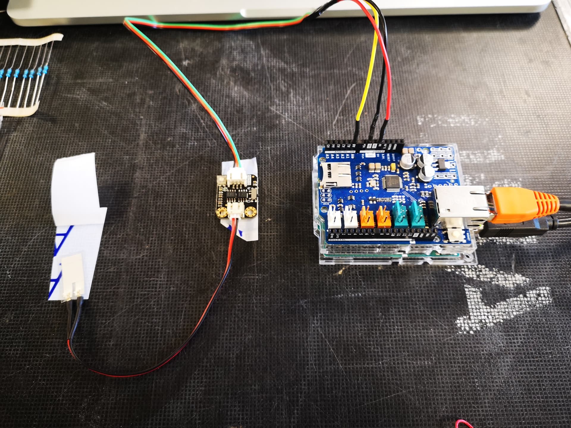
Can you show a photo with the wiring ?
If you have a multimeter, then you can measure the voltage over the piezo element.
Can you tell what your project is about ? Please give us a broader view. Because I wonder in what situation this module can be useful. It is fun to try, but that's about it.
Replying to this and xfpd.
Wires are colour coded and 5v and GND are red and black so wired correctly, green wire goes to the analouge input although it is blue in the wiki. Can try and transpose them to see if it makes a diference.
As per the instructions on the wiki, the switch was set to 'D' although connected to the analog inputs. Setting it to 'A' is just a stream of values between 300 and 800 and again, touching the piezo film or even removing it made no difference to the output. I sholud note that I bought 3 of these and all react the same. Also have 2 Arduinos and tried with both.
The project is at where I work so will add the output tomorrow whan I am back but with the sensitivity pot all the way up it is just a stream of 1023 and all the way down it is fluctuating between 16 and 17. inbetween it randomly shows either. touching or removing the piezo film makes no difference.
The broader picture is to find a sensor that I can attach to something, piece of wood or some structure and will detect someone knocking or tapping it and then act upon that.
I have tried piezo elements but cannot get them to work reliably. I thought this may be a better option but open to suggestions.
I have updated the post with a picture of the setup and screenshot of output. The output is unchanged when flexing / touching the film or even with it unconnected.
The 1023 is as HIGH/1/5v when you use D(igital output) with "17/18" as LOW/0/0v. The 17/18 should be zero, so you have a grounding problem or your sensor has an internal ground problem.
Ok, thanks. I won't have a chance to look at it again until Monday but I bought 3 of these and all are the same so unlikely an issue with the sensors unless it is a faulty batch.
The Wiki page for this that is linked in the post has 1023 an 11 as the values from the digital output.
I suspect this is not the correct thing for the application in mind but as I have them I am still interested in getting them to work for some potential future use.
The white plastic knob to the <- left of the three-pin connector might be a trimming potentiometer that possibly could get "11" down to "0" - check your sensor documentation.
Now that you know the output, you can create the program(s) to use that output in your project.
The knob is a trim pot and adjusts sensitivity, all the way up the output is a constant 1023 and all the way down is a constant 16 but again, does this without the film connected.
I Will check for earth problems but I doubt that is the issue.
Probably just write code that "maps" the known range to a range you want... for example, you know the sensor will give you 11 to 1023... and if you want to make the output range 0 to 100...
value = map(analogRead(sensorPin, 11, 1023, 0 100); // pin, min input, max input, min output, max output