Hey everyone! I'm kind-of-ish new to Arduino (noob) and am wondering if you guys can help me out with this project. It might be a bit above me, but I can do it!
Anyways, since I have an Uno I think I have to use the Software Serial option for that shield.
I have inserted my SIM card into the shield
I have plugged in the TX and RX shield jumpers to the correct UNO inputs.
I have run this sketch:
//Serial Relay - Arduino will patch a
//serial link between the computer and the GPRS Shield
//at 19200 bps 8-N-1
//Computer is connected to Hardware UART
//GPRS Shield is connected to the Software UART
#include <SoftwareSerial.h>
SoftwareSerial GPRS(7, 8);
unsigned char buffer[64]; // buffer array for data recieve over serial port
int count=0;     // counter for buffer array
void setup()
{
 GPRS.begin(19200);               // the GPRS baud rate
 Serial.begin(19200);             // the Serial port of Arduino baud rate.
}
void loop()
{
 if (GPRS.available())              // if date is comming from softwareserial port ==> data is comming from gprs shield
 {
   while(GPRS.available())          // reading data into char array
   {
     buffer[count++]=GPRS.read();     // writing data into array
     if(count == 64)break;
 }
   Serial.write(buffer,count);            // if no data transmission ends, write buffer to hardware serial port
   clearBufferArray();              // call clearBufferArray function to clear the storaged data from the array
   count = 0;                       // set counter of while loop to zero
 }
 if (Serial.available())            // if data is available on hardwareserial port ==> data is comming from PC or notebook
   GPRS.write(Serial.read());       // write it to the GPRS shield
}
void clearBufferArray()              // function to clear buffer array
{
 for (int i=0; i<count;i++)
   { buffer[i]=NULL;}                  // clear all index of array with command NULL
}
But alas, I get NADA on the Serial Monitor! NOTHING! What is wrong help me please! :o
Thanks so much! But if you look at the instructions link on the original post, you will see that the shield in those instructions is green. The shield in your instructions is white. Is there a difference? (I have the green one as I said in the original post, so will your instructions work?)
Yes, they are all the same, Arduino compatible, it worded ok on my 'green' board.
Two things to note , as detailed in the Geeetech site, the Sim900 needs up to 2 amps peak, so its not really suitable for being powered from the Arduino, you need the feed the shield with an external supply / change the voltage selector switch as well
Though it needs 2 amp, its often only for a second or two, I found for testing a 1A 5v wall wart supply with a 1000uf capacitor on its output worked ok.
The default for the Sim shield is to be turned on and off by the switch on the board; its better to software control that, but you need to change that soldered jumper JP.
So I am going to plug in an external battery (Would it be OK to use a 9V battery?)
Should I solder JP or not? It came un soldered.
As for jumpers, I have the RX and TX plugged in to D7 and D8
Think you need to read those Geetech instructions again.
You cannot use a 9v battery as the board specifies 5v input only, so you need to use a regulator of some type.
Have a look around, most folk have a pile of old chargers around, you just need one thats 5v and at least 1A.
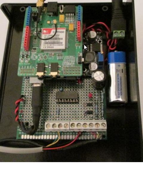
Like that picture I posted of mine, using a 9v battery for backup, BUT the battery runs though that little Step down converter , set to produce 5V even when the battery is below 5v.
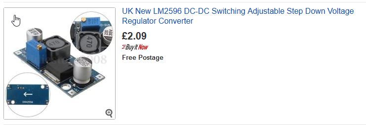
If you only have 9v or 12v supplies then you need one of those little step down coverters or a simple 7805 regulator.
When you have your software running properly is best to have the software controlling the shields on/off functions to save power, but you can run as it is now, having to manually switch it on/off.
You just need a dab of solder on an iron to bridge the JP pads.
The jumpers for those Tutorials use D7 and D8 in Software Serial mode
I know this is stupid. But remember, I'm learning. And I'm a fast-enough learner, don't count me out yet.
Explain this to me step by step. Pretend I just got my GSM Shield out of the shipping box. Please, explain step by step in the most basic way possible what I do with all this (The Arduino uno, the solder, the shield, etc.) Pretend everything is fresh out of the box. What do I do, step by step. Pretend I am a 5 year old when explaining!
Also, one thing I do not get from the Tronix website is weather to solder JP or not. I am unsure about that.
According to Tronix, we will be using the Software Serial thing and according to Geetech in order to use Software Serial we ARE supposed to solder JP. This leads me to believe that I should solder JP, but I'm not sure!
I mentioned the 7805 because thats often easily bought from a local shop; but if you have to mail order then its probably better to go for one of the dc converters like the newer type you show, or one of these like I use.
You can buy them one at a time, though 2/3/4/5 can often be good buys.
Their main advantage is they use little power themselves so do not run hot or use a lot of battery power.
There are two distinct types the step down type that you show, which will produce the output voltage as long as the input voltage is greater.
The other type is the step up and down type, if the input voltage falls below the output voltage, they are still able to produce the output voltage by stepping Up the input voltage; handy for getting the best life out of a battery.
If you do use a 9v battery a little one like a 6LR61 will only last for a few minutes of Sim900 calls.
As for JP, if you see the Tronix tutorial, the first part where he shows fitting and testing the sim card there he uses the one board power button, so at that point he has not soldered JP.
In the following testing sketches he uses Software to control the boards On/Off line, so clearly he has shorted JP with a solder bridge.
If you look at the code you can see these lines which turn it on /off
void SIM900power()
// software equivalent of pressing the GSM shield "power" button
{
digitalWrite(9, HIGH);
delay(1000);
digitalWrite(9, LOW);
Edit - looking at his tutorial again, perhaps his board has a slightly different Power button wiring as I cannot see JP, though just do as I mentioned above, test out the board to see if the Sim card and Board can connect to the network ok, as indicated by the flashing led.
Once proven, power off, then solder JP and run the test sketches using software control
ricky101:
I mentioned the 7805 because thats often easily bought from a local shop; but if you have to mail order then its probably better to go for one of the dc converters like the newer type you show, or one of these like I use.
But my problem is that the Arduino is not detecting the board at all. It doesn't ever say ANYTHING on the Serial Monitor. Is that caused by voltage problems?
ricky101:
If your are waiting on the DC Converters what are you powering the Sim900 shield with ?
If you have some other 5v power source, what code are you running on the Arduino ?
All I did was slap the GSM shield on top of the UNO, saw the green LED (on the shield) light up, pressed the on-shield button for a few seconds and watched the red LED blink. That is ALL I did. I assume the shield is drawing power from the Arduino board. I mean, where else?
stupid-questions:
But my problem is that the Arduino is not detecting the board at all. It doesn't ever say ANYTHING on the Serial Monitor. Is that caused by voltage problems?
//Serial Relay - Arduino will patch a
//serial link between the computer and the GPRS Shield
//at 19200 bps 8-N-1
//Computer is connected to Hardware UART
//GPRS Shield is connected to the Software UART
#include <SoftwareSerial.h>
SoftwareSerial GPRS(7, 8);
unsigned char buffer[64]; // buffer array for data recieve over serial port
int count=0;     // counter for buffer array
void setup()
{

 pinMode(9, OUTPUT);
 digitalWrite(9,LOW);
 delay(1000);
 digitalWrite(9,HIGH);
 delay(2000);
 digitalWrite(9,LOW);
 delay(3000);

 GPRS.begin(9600);               // the GPRS baud rate
 Serial.begin(9600);             // the Serial port of Arduino baud rate.
}
void loop()
{
 if (GPRS.available())              // if date is comming from softwareserial port ==> data is comming from gprs shield
 {
   while(GPRS.available())          // reading data into char array
   {
     buffer[count++]=GPRS.read();     // writing data into array
     if(count == 64)break;
 }
   Serial.write(buffer,count);            // if no data transmission ends, write buffer to hardware serial port
   clearBufferArray();              // call clearBufferArray function to clear the storaged data from the array
   count = 0;                       // set counter of while loop to zero
 }
else {
  Serial.print("no");
}

 if (Serial.available())            // if data is available on hardwareserial port ==> data is comming from PC or notebook
   GPRS.write(Serial.read());       // write it to the GPRS shield
}
void clearBufferArray()              // function to clear buffer array
{
 for (int i=0; i<count;i++)
   { buffer[i]=NULL;}                  // clear all index of array with command NULL
}
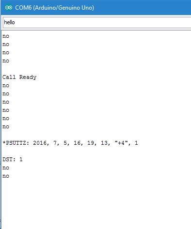
First thing it seems you have changed the buad rates from the original geetech code ? , plus I have added a delay and newline code so you can read the output properly.
You must change the Serial monitor to 19200 as well.
It gives the same output regardless of the Sim card being in or out.
Have you soldered JP, the code uses software power control, so if you have not soldered JP and first press the powerbutton, when the code runs, it then turns the sim board off; if it does, press the PowerKey again and it should start transmitting.
Watch the RED led, it should remian ON while you do the testing.
//Serial Relay - Arduino will patch a
//serial link between the computer and the GPRS Shield
//at 19200 bps 8-N-1
//Computer is connected to Hardware UART
//GPRS Shield is connected to the Software UART
#include <SoftwareSerial.h>
SoftwareSerial GPRS(7, 8);
unsigned char buffer[64]; // buffer array for data recieve over serial port
int count=0;     // counter for buffer array
void setup()
{

 pinMode(9, OUTPUT);
 digitalWrite(9,LOW);
 delay(1000);
 digitalWrite(9,HIGH);
 delay(2000);
 digitalWrite(9,LOW);
 delay(3000);

 GPRS.begin(19200);               // the GPRS baud rate
 Serial.begin(19200);             // the Serial port of Arduino baud rate.
}
void loop()
{
 if (GPRS.available())              // if date is comming from softwareserial port ==> data is comming from gprs shield
 {
   while(GPRS.available())          // reading data into char array
   {
     buffer[count++]=GPRS.read();     // writing data into array
     if(count == 64)break;
 }
   Serial.write(buffer,count);            // if no data transmission ends, write buffer to hardware serial port
   clearBufferArray();              // call clearBufferArray function to clear the storaged data from the array
   count = 0;                       // set counter of while loop to zero
 }
else {
  Serial.println("no");

 delay (2000);
}

 if (Serial.available())            // if data is available on hardwareserial port ==> data is comming from PC or notebook
   GPRS.write(Serial.read());       // write it to the GPRS shield
}
void clearBufferArray()              // function to clear buffer array
{
 for (int i=0; i<count;i++)
   { buffer[i]=NULL;}                  // clear all index of array with command NULL
}
ricky101:
First thing it seems you have changed the buad rates from the original geetech code ? , plus I have added a delay and newline code so you can read the output properly.
You must change the Serial monitor to 19200 as well.
It gives the same output regardless of the Sim card being in or out.
Have you soldered JP, the code uses software power control, so if you have not soldered JP and first press the powerbutton, when the code runs, it then turns the sim board off; if it does, press the PowerKey again and it should start transmitting.
Watch the RED led, it should remian ON while you do the testing.
//Serial Relay - Arduino will patch a
//serial link between the computer and the GPRS Shield
//at 19200 bps 8-N-1
//Computer is connected to Hardware UART
//GPRS Shield is connected to the Software UART #include <SoftwareSerial.h>
SoftwareSerial GPRS(7, 8);
unsigned char buffer[64]; // buffer array for data recieve over serial port
int count=0; // counter for buffer array
void setup()
{
GPRS.begin(19200); // the GPRS baud rate
Serial.begin(19200); // the Serial port of Arduino baud rate.
}
void loop()
{
if (GPRS.available()) // if date is comming from softwareserial port ==> data is comming from gprs shield
{
while(GPRS.available()) // reading data into char array
{
buffer[count++]=GPRS.read(); // writing data into array
if(count == 64)break;
}
Serial.write(buffer,count); // if no data transmission ends, write buffer to hardware serial port
clearBufferArray(); // call clearBufferArray function to clear the storaged data from the array
count = 0; // set counter of while loop to zero
}
else {
Serial.println("no");
delay (2000);
}
if (Serial.available()) // if data is available on hardwareserial port ==> data is comming from PC or notebook
GPRS.write(Serial.read()); // write it to the GPRS shield
}
void clearBufferArray() // function to clear buffer array
{
for (int i=0; i<count;i++)
{ buffer[i]=NULL;} // clear all index of array with command NULL
}
So let me get this straight... what I should do is THIS:
Upload this new code to the Arduino
Solder JP
Plug in the shield
Power on Arduino
5.Power on shield by pressing button
And then from there it should work? That is all I need to do to make it work?