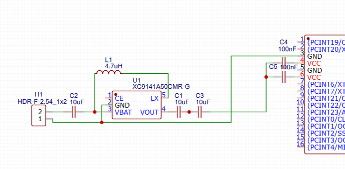
Hi! I want to verify if what I have done till now is correct, this is just a simple circuit for controlling a servomotor(that is not pulling anything) on a Atmega328P-AU microcontroller using an XC9141A50CMR-G voltage regulator, I checked the datasheet but I didn't understood a lot from it. I want to make a custom pcb from this, and I want to know if to continue or if there are any mistakes that need to be repaired.
Do exactly as they show in the datasheet
Read the NOTE ON USE section in the datasheet and follow the layout examples.
Vout connects to the 328P Vcc
well that is the same wiring as I did right?
Do I need resistors for switches? The microcontroller has internal ones right?
Other modifications I made, 2 switches, 1 button and 1 LED on pins 2,3,4,5 and servo on pin 9. Is everything allright?
No.
Also there need to be two 10uF capacitors connected to VOUT
From the data sheet GRM188R60J106M x 2
No
Each Vcc pins need to be connected and each needs to have a 0.1uF capacitor connected to it and ground.
The regulator wiring is still wrong.
You need to read and understand the datasheets for the parts you are using.
I hope that now everything is right, in the supplied datasheet I couldn't not find anything about 0.1uf capacitors on the VCC pins..
Wrong.
@jim-p posted DS example schematics.
Each power pin on ATmega32P should be decoupled by 100nF capacitor. It means connected between power and GND as close as it is possible.
Yes like that but you have plenty more to do
Well, this is the circuit to power the board right?Now I can add 2 switches on pin 3 and 4, 1 button on pin2, 1 led with a resistor on pin 5 and 1 servo on pin 9 like in the picture
Why are you showing an old schematic that I already said is wrong.
Please take some time and check you schematics
I edited the comment, and now there are 2 new photos
Please take some time to check your schematics and what you are posting here.
I checked my schematics but I don't know if everything is allright that's why I asked you..
No. I see nothing there that involves power.
The schematics are unreadable.
I suggest that you read some tutorials on basic electronics and circuit design before you go any further.

This involves powering the microcontroller, but I forgot to connect the GND


