Hi, I want to control a single motor using H bridge ( 4x 2n3904) but the problem is I cant increase the current flowing on my motor even I decrease the Rb the transistor just overheat... I have 12V transistor supply and a 5V driving voltage
I want to have atleast 100mA flowing on my motor... in the circuit i replace the motor with resistor equivalent since when i run the motor through a direct 12V the current is about 94~100mA...
Hi, because you are only using 5V as the signal you are not turning Q1 or Q3 fully ON, their base emitter current will be dependant apon the voltage at the emitters, this is the voltage dropped across your 127R resistor in the circuit, or your motor in real life.
So while you turn Q2 and Q4 ON because their emitters are at gnd, Q1 and Q3 are not fully ON, they are limiting the current to your load or motor.
By the way do you have the gnd of the 5V supply connected to to gnd of the 12V supply, this is essential.
On the simulation, place a voltmeter from gnd to Q1 emitter and turn it ON. (This should measure 5-0.7=4.3V)
Place a voltmeter on Q4 collector and gnd and turn it ON.(This should measure about 0.2V)
Tom.....
You need to use PNP transistors in the upper part of the bridge. You also need diodes to protect the transistors from inductive spikes (when using a motor). 2N3906 PNP transistors will work for a small motor.
Each switch must be in common-emitter configuration to be efficient, as you have it the
top switches are emitter followers which will obviously overheat as this is very inefficient
for switching power. High side common-emitter switches must be PNP, low side must be
NPN.
Alternatively you can generate a bootstrapped voltage rail above the +ve supply to enable
NPN to be in common-emitter.
The same principles apply to MOSFETs, n-channel for low-side, p-channel for high-side,
or a bootstrapped rail to allow n-channel in the high-side. Its easier for MOSFETs as there
are many driver chips that will enable high-side n-channel switching for MOSFETs, not
many for NPN (which require far larger currents).
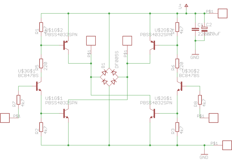
Here's a BJT H-bridge circuit - note the two auxiliary transistors than turn on a pair
of high-side and low side switches together (so only two control wires needed) and the
bridge rectifier providing all the flyback diodes in one package
Yes the layout is odd, the arms of the bridge are crossed over X-style in the middle,
and you have to tune the values of R5 and R6 according to the supply voltage and
the gain of the transistors.
The two control lines must not be pulled HIGH simultaneously, this circuit has
no shoot-through protection for that.
MarkT:
Here's a BJT H-bridge circuit - note the two auxiliary transistors than turn on a pair
of high-side and low side switches together (so only two control wires needed) and the
bridge rectifier providing all the flyback diodes in one package
Yes the layout is odd, the arms of the bridge are crossed over X-style in the middle,
and you have to tune the values of R5 and R6 according to the supply voltage and
the gain of the transistors.
The two control lines must not be pulled HIGH simultaneously, this circuit has
no shoot-through protection for that.
I cant understand well the circuit... where should i put the motor and can it be control using PWM
Connect the motor to the two central squares in the above schematic diagram.
Yes, you can use PWM to control the H-bridge. The control inputs are connected to R7 and R8.
MarkT:
Here's a BJT H-bridge circuit - note the two auxiliary transistors than turn on a pair
of high-side and low side switches together (so only two control wires needed) and the
bridge rectifier providing all the flyback diodes in one package
Yes the layout is odd, the arms of the bridge are crossed over X-style in the middle,
and you have to tune the values of R5 and R6 according to the supply voltage and
the gain of the transistors.
The two control lines must not be pulled HIGH simultaneously, this circuit has
no shoot-through protection for that.
Hi,, im gonna use this .. for a 12V supply and 5V PWM signal should i use power transistor like TIP31C and TIP32C or I can just use 2n3906 and 2n3904..
you say R5 and R6 will tune the hbridge but how can i compute it to have atleast 100mA current flowing... is the value of R1-R8 except R5 and R6 fixed in 4.7kohm?
You have to do the maths for your particular devices, in particular work out the
saturation voltages and thus dissipation for the switching devices for various base
currents and choose a suitable base current - that then determines R5 and R6.
If you read the part numbers you'll see I used surface mount superbeta devices with
very nice specs - 2N3906 etc cannot begin to compete. Darlingtons would be feasible
at 12V (not really for 5V though), which makes the drive requirements easy.
This circuit was developed for small hobby motors for little robots, and to be physically
small (with surface mount parts about 2cm x 2cm)
Is that 100mA under load? What is the stall current?
Your transistors need to be able to handle the stall current. More, if this will -ever- switch directions. You could end up in the situation where the motor is spinning full speed one way, and the Arduino switches direction. So you'll have both 12V applied, plus nearly 12V generated by the motor in the opposite polarity.
I would not have confidence in a 2N3904 to handle that, especially if that is 100mA without a load.
I really cant get it to work Im using TIP31C and TIP32C
im using this circuit
I use 220ohm resistor
also when i try to configure TIP32C , 12V in emitter motor in collector its always on even its grounded or in 5V signal it will of only wen i disconnect the source in the base
No idea what voltage or current levels you are expecting with the TIP31C / TIP32C -
220 base resistor is probably far too large.
Most old-style power transistors like this (not Darlingtons) have abysmal
current gain at high currents and only saturate when the base current is 1/10 to 1/6th
of the collector current.
No-one ever uses them these days, MOSFETs and super-beta devices outperform them
in every respect. These TIP devices are around 40 years old!
MarkT:
Here's a BJT H-bridge circuit - note the two auxiliary transistors than turn on a pair
of high-side and low side switches together (so only two control wires needed) and the
bridge rectifier providing all the flyback diodes in one package
Yes the layout is odd, the arms of the bridge are crossed over X-style in the middle,
and you have to tune the values of R5 and R6 according to the supply voltage and
the gain of the transistors.
The two control lines must not be pulled HIGH simultaneously, this circuit has
no shoot-through protection for that.
I tried this circuit using BD139,BD140 and 2n4401 and it works perfectly ! ! thank you


