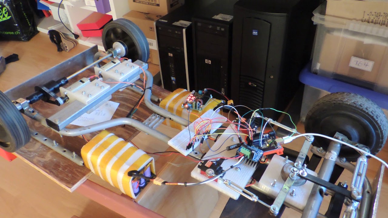
knightridar:
@Semtex9
So that seems like you could power a 36 kW rated motor with that h-bridge.
Is there any book you would recommend regarding info for these things?
What is the purpose of 4, 15V transformers?
I'm guessing the optocouplers work similar to the way they work on relays?
Is IRF a brand of brushless drivers?
Any chance you can provide a link on digikey or something?
Thanks.
@ballscrewbob.
Thanks I PMed him to see if he can respond to the post.
Also this might be useful for the board DrAzzy provides on Tindie.
Welcome, IHI Connectors & mechanical wire & cable lugs
Single Wire Lugs, 1 Wire Termination per Lug
American wire gauge - Wikipedia
The board connectors on DrAzzy's board are rated only up to 40A.
The ones above have higher current ratings but may cost slightly more per unit and there are regular and SMT versions too.
https://www.tindie.com/products/drazzy/4-channel-logic-level-mosfet-driver-100a-up-to100v/
Ok sry for not responding, 4 transformers galvanic insulate the gate drivers from one another, since high and low emitters get to different voltages, and you need 15 V between gate and emitter(igbt).
If you tried to fire a pair with one grounded psu, you would ground high emitter together with a low one, and get a very nasty short between high emitter that gets to the DC rail 100V when it fires, and low emitter that is DC rail ground. 2 of my gate driver psu grounds float to the high emitter voltage while other two are grounded with DC rail ground, all are separated, its not ideal, but it works fine.
I have no pictures yet because I am still working on it.
I wouldn't go above half the rated power, fused it at 25A, but theoretically yes its beefy.
IR is International Rectifier, brand for IC, like Fairchild or toshiba, sorry, take a look at this one IR2136, and search for International rectifier application notes for that IC, to get an idea on different driver designs.
2 more problems are that gates require higher energy on higher duty cycle frequency, and that if you select a wrong gate resistor or long gate lead, the capacitive gate can resonate with inductive lead, and turn the igbt on and off repeatedly for 1 pulse if it charges too fast ie resistor too small, or if it charges too slow ie too big a resistor, it will heat fast, and that can also destroy your stuff. With mosfets or igbt it is crucial that you ground the gate when you want it to turn off fast, that's why i use tlp251 flip-flops, and if you set a diode antiparalel to gate charge resistor, you can go even faster.
Another fact is that you will need to design some good protections so that if things go wrong your circuit dosen't explode. "kassakian: principles of power electronics" is a good read, also "Inaustrial Power Engineering and Applications Handbook by K.C.Agrawall". Higher the power rating more prediction needed. Account for overvoltage, overcurrent, missfire, RF interference due to very high currents being pulsed, reactive load transients, and anything else that you can think of. If that thing explodes, you can get seriously hurt, or start a fire. Protect yourself while testing, and be SURE any HV capacitors are empty when you touch the rail, they will take your hand off.
You might need to account for inrush current when you plug that thing in, depending on design because you might need a lot of capacitors, to stabilize the DC rail. One way to limit inrush is with ptc or ntc thermistor, bypassed with a relay when the capacitors charge up. If you are using batteries to get 100V those have their own set of dangers to prepare for, and design protections.
Arduino uno can barely drive it in my case because i got an lcd, and pid, and a keyboard, and it uses only two channels so i can't achieve full controll by all quadrants, but I drive a welder, you would need to be able to control igbt-s individually so you can brake, or set the motor in idle. I can send you the spwm code with variable amplitude and frequency that I found, but you will need to work on it some more for full control.
Oh, and optocouplers are used kind of like fast solid state relays because I have 4 different grounds/commons. 1 is main dc rail, together with two of the gate drives are also on it, other 2 commons are for 2 high emitters, and their gate drivers, 4 is the arduino ground that is powered independently, so that arduino is nowhere near the power output side. Optos are also good protection for your control logic, since they can insulate 5000V, while transmitting the signal, only down side is a small delay because they are not nearly as fast as cmos, but its ok up to a couple of mhz, and you will aim way lower than that for your duty cycle.
100V 100A is no joke, you will need to get very serious if you want to do it, or purchase professional igbts with drivers already on them, but those cost a ton, and you might fry them. I recommend you build a smaller scale system for testing first.
