I need this relay to open electrolock, which is powered with external 12V.
To to so i have connected external 12VDC power adapter (12V/1A ).
This is current connection:
JD-VCC ---> 12V positive, from power adapter
GND --> GND from power adapter
VCC ---> 5V ardouno pin
GND --> GND pin of arduino
IN1 --> signal pin on arduino.
As test i have connected signal pin to arduino GND and then to 5V pins ( low / high state ), but there's no relay click.
Any suggestion what's wrong with this setup ?
Btw. because i can not change installed AC electro lock to my DC lock,
i will use existing AC lock an if needed i can set stronger power adapter...
Arnix
Sainsmart relay boards usually need the control pin to be pulled low (to ground) to actuate the relay.
Sorry guys for late reply !
I was spending some time with kids and xmas preparations are on the way
So... i made tests based on https://ibb.co/h6W5H6 connection and this is how it looks.
Without controller:
Diode -- 12V both sides
Transistor emitter -- 12V
1K resistor --> 0V both sides
With arduino controller
rest of the readings are the same ( regardless the state of signal pin )
It looks that diode is burned out ? ( 0.25V )
btw. i try to resolder it to NO but the situation is the same. Instead of 12 i get 0V regardless if the state is low or high... But, all this is quite strange because if the diode has burned out, that means it will blow again...
This is some strange thing or am to hungry to continue :-). So am going to make some lunch break
I made complete new board but the situation is totally the same.
If i connect power supply i get this:
NO --> COM = 12V
NO --> door lock GND = 0V
COM --> door lock GND = 12V
when the controller is connected i can read correct 5V value ( 4,30V ).
there's no voltage on diode and no voltage on transistor...
So this signal should activate relay but there's no short between NO and COM.
UPDATE:
i found one faulty connection. I will retest all in 10 minutes
unfortunately no changes, it's the same as described before...
am gonna make some tests with the old board and i will change diode / transistor
ok, i have no more ideas what can be wrong. I have tested direct connection (
Signal= 5V/GND ,
GND = GND/ GND from battery ,
12V = +12V from battery,
but there is no "click" sound...
Hi,
Please using this image for reference and using A, B, C, etc
List
Voltage A
Voltage B
Voltage C
Voltage D
Voltage E
With respect to gnd.
Do it with the 12V coil power, but no Arduino.
Do it with the Arduino connected, but not trying to actuate the relay.
Do it with the Arduino connected, and trying to actuate the relay.
You should then be able to give us 3 sets of 5 voltages.
PLEASE use the A, B etc as reference in your reply post.
Do Not at this stage worry about any voltage measurements to the Lock.
Hi Tom.
Thank you very much for your time and effort.
I didnt, change the components on this board, i just re solder few connections and i can hear click when i apply 5V to signal line !
OK, i'v connected the battery like
+12V --> 12V pin on relay board
12V --> GND pin of relay board
12V --> Arduino GND
////////////////////////////////////////////////////////////////
This are the results ( Arduino is not connected )
Voltage A ( 1K resistor )
0 V
Voltage B
0 V
Voltage C
12V
Voltage D
12V
Voltage E
12V
////////////////////////////////////////////////////////////////////////
Do it with the Arduino connected, and trying to actuate the relay.
Voltage A ( 1K resistor )
4,6 V ( so signal is passing to relay board
Voltage B
0,82 V
Voltage C
0.10V
Voltage D
0.10V
Voltage E
12V
/////////////////////////////////////////////////////////////////////////
How to setup lock? There is no short between NO - COM, when the signal is triggered...
Hi.
Okay so your transistor is working.
What voltage do you have if you measure directly on the relay coil pins, with the activation ON.
You should have 12V across the relay coil.
It's interesting but i get short between NC and NO lines, when the signal is 5V.
When i remove it, there are no shorts. So i can use this as positive side for connecting lock.
But i dont understand why i dont have shorts between COM line...
I will use it and as additional test am gonna measure resistance between pins.
Just two more things
1.)I have pulled one wire from NC / NO contact i have put this wire on positive side of lock
GND is pulled from main GND pin of the relay board ( connected to main power supply )
The problem is that i dont get any reading but i think that's because am getting impulse and not voltage. If this is the case, how to connect lock so that i have 12V on lock terminals, when relay trigerrs ?
2.)
For tests i have used DC lock but real on is solenoid "AC" lock.
There should not be any problem with it ?
I have tested this AC lock directly with 12VDC power adapter and it has worked OK.
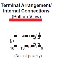
The printing on the top is the bottom view.
Not that it matters much - you put current thru the coil, it will energize and close the contacts: 4 to 8, and 13 to 9.
The contacts should switch AC on & off ok.
You're not putting AC thru the coil, are you?
I will use it and as additional test am gonna measure resistance between pins.
Just two more things
1.)I have pulled one wire from NC / NO contact i have put this wire on positive side of lock
GND is pulled from main GND pin of the relay board ( connected to main power supply )
The problem is that i dont get any reading but i think that's because am getting impulse and not voltage. If this is the case, how to connect lock so that i have 12V on lock terminals, when relay trigerrs ?
2.)
For tests i have used DC lock but real on is solenoid "AC" lock.
There should not be any problem with it ?
I have tested this AC lock directly with 12VDC power adapter and it has worked OK.
3.)
The contacts should switch AC on & off ok.
You're not putting AC thru the coil, are you?
***Main test supply is 12V/7Ah battery but for real installation am planning to use 12V/2A power adapter...
"1.)I have pulled one wire from NC / NO contact i have put this wire on positive side of lock"
Huh? You should one AC line going to the COMMON pin, say the one marked "4" in reply #32, and the other line from the NO pin, say the one marked "8".
Then when the relay is energized, the contact is closed and your device turns on.
If you have a Sainsmart relay board in there instead of a standalone relay as pictured in #32, then you're really just concerned with the AC connection part, where the relay is acting like an open/close switch in one lead of the AC power cord.
Am running low on battery :-)...
I will use this design from post 32.
But there is no AC source.
Relay board is powered with 12V DC and this same 12VDC power adapter should activate lock.
Relay should short positive wire and pass voltage to lock ( when the signal line is HIGH ).
GND wire of lock is connected to GND of power supply.
Relay just needs to short positive end and pass voltage thru lock, when signal line is High.
Appears you are connected to the NC relay contacts, pins 13 to 11, (closed when the relay is NOT energized), is that what you intended? NO contacts are pins 13 to 9.