Is it possible that the TX LED on the arduino Pro Micro is causing the hall sensor to detect these changes ? Would this be the source of the background noise ?
I noticed that the decrease in the mV value is in sync with the TXLED pulsing pattern...
I won't go and wonder what it could be since I'm just a beginner here.
The steady value is 2.93V but it drops to 2.88V and 2.63V in a constant rhythm.
Some of you with more experience in eletronics may help me figure this out.
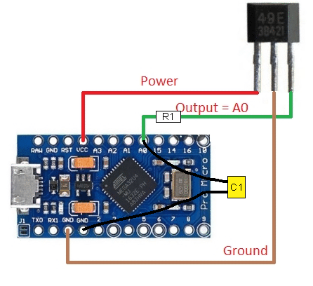
My first suggestion is to add a capacitor from A0 to the nearest ground.
Probably a 0.1 µF
Analog signals do not look like the book, they have noise on them. The Arduino takes the equivalent of a flash photo catching only an instant of the voltage. Any spikes occurring at the sampling time will be converted causing errors.
The 0.1µF capacitor acts like a shock absorber on the voltage line.
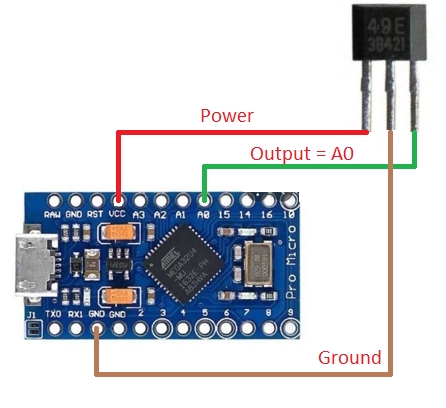
I believe that sensor needs a pull up resistor btwn signal and 5v, can you post your code and confirm if you do have a pull up resistor either in the code or in the circuit (I don't see that)
#include <Joystick.h>                //Joystick Library 2.0 by MHeironimus
#define pinHall A0                    //Hall sensor into the analog pin A0

//ID, Type, Buttons, Hat, various axis. True only for Rotation X Axis.
Joystick_ Joystick(0x12, JOYSTICK_TYPE_JOYSTICK, 1, 0, false, false, false, true, false, false, false, false, false, false, false);

const bool initAutoSendState = true;


void setup() {
  pinMode(pinHall, INPUT_PULLUP);
  Joystick.begin();
   Joystick.setRxAxisRange(730,1023);   //To set the range of the moving axis
  Serial.begin(9600);}


void loop() {

int RxAxis_ = 0;

  //we measure 10 times and make the mean
  long measure = 0;
  for(int i = 0; i < 10; i++){
      int value =
     RxAxis_ = measure += analogRead(pinHall);
 int mapped = map(RxAxis_, 0,1023,730,1023);

  measure /= 10;
  //voltage in mV
  float outputV = measure * 50000.0 / 1023;
  Serial.println(outputV);
  Serial.print(" mV ");
  delay (100);
  Joystick.setRxAxis(RxAxis_);

}}
Hall effect sensors are sensitive to stray magnetic fields. Their working principle relies on detecting magnetic fields, and any external magnetic field can result in spurious readings. It's their Achilles' heel. This is in addition to voltage fluctuations as @JohnRob mentions.
If you look at professional-designed sensor circuits, you'll generally come across a lot of circuitry around a sensor used for so-called signal conditioning, which basically boils down to managing all kinds of contingencies and external factors that make a real sensor signal deviate from what it's theoretically supposed to be. Sensor frontend design can be pretty complicated, especially for high-sensitivity sensors.
Would you be kind enough to guide me how to introduce this capacitor into the circuit ? As I mentioned, I'm pretty new to this haha.
A very simple diagram would help me tremendously!
Oh sorry, you of course meant to decouple the signal line. Yes, that will work as well. I'd also recommend decoupling the Vcc to the sensor.
Ensure to keep C1 fairly small; I think 100nF is really the upper limit. I'd go for 10nF probably. Otherwise it'll make the sensor rather slow to respond.