Hi again,
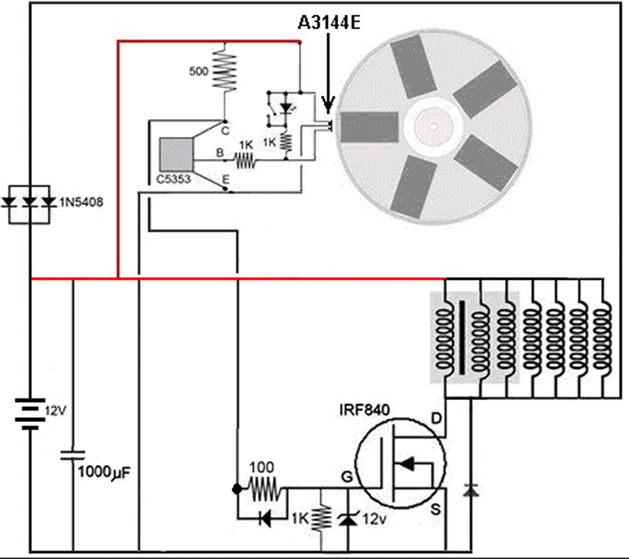
I have attached a new jpg to show the full circuit. What is supposed to happen is that the 5 rotating magnets trigger the Hall Sensor 5 times per rotation such that a current flows through the MOSFET and coils creating a magnetic field in each solenoid. When the current shuts off suddenly (as each rotor magnet passes the sensor) the field collapses and creates a high back emf pulse that is fed through the 3 diodes to the battery. I can look at those on a scope for my research purposes.
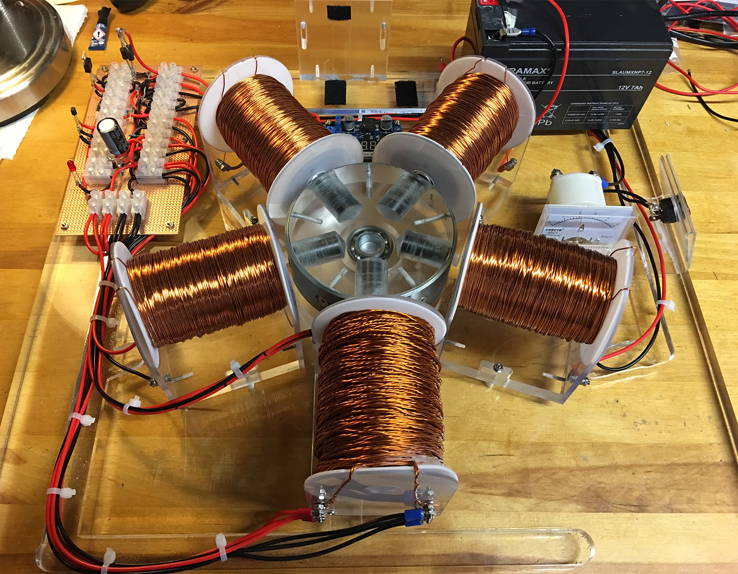
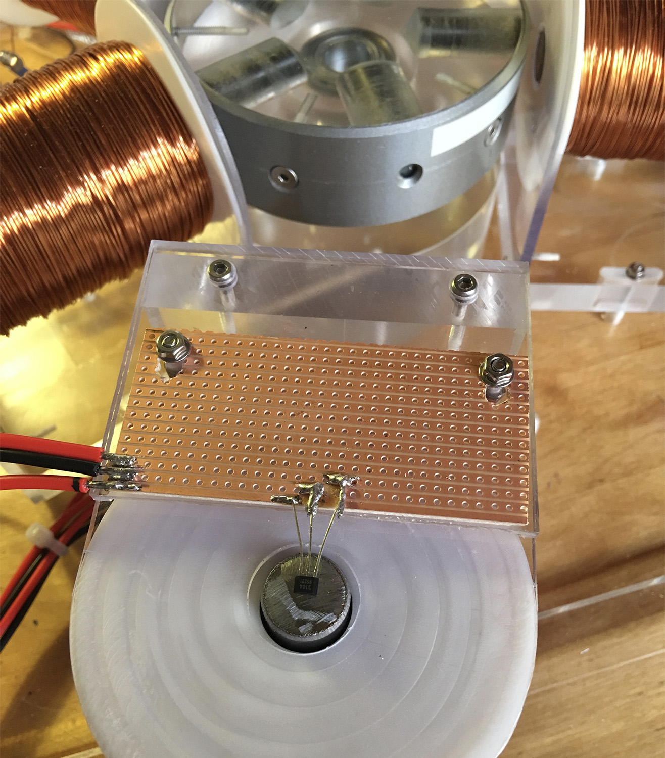
Three of the coils are wound on one coil of 'litzed' wire (nearest camera) and the others are on their own spools and all have a steel core. The Hall sensor position is attached to the front of the spool with the 3 coils on it and shown in one pic and the whole assembly in the other pic (Back EMF Generator).
If you think the circuit will not do what I am hoping would you be able to suggest how to modify it?
Any help would be appreciated. ![]()
Jules