Hall Sensor Throttle & Brake pedals for RC car

Hello! All the best for 2022!

Skill level: Advanced starter, more creative thinking less logical thinking regarding problem solving. I copy paste parts of code and sometimes it works. Usually not.

I hope somebody can help me. I am trying to write a sketch for controlling an RC car with separate throttle and brake pedals via one PWM signal. My skills regarding feeding an all-in-one Arduino PPM stream into the trainer port of my radio is way beyond my knowledge. So for starters I'm going to feed the PWM signal into a PWM-to-PPM converter of which I have positive experiences with. (I hooked up a servo tester this way and BAM, I added an extra control knob to my radio)

I am using affordable $10-$15 Hall sensor pedals from Aliexpress. So far I received one, the rest is in de mail on a slow boat.

The problem: The servo goes in one direction for a bit, then sweeps all the other way when the Hall sensor is connected to A0. The same behavior applies for connecting the hall sensor to A1.

Is this because the Uno expects signals on both A0 and A1? As I have only one pedal atm, I switch between A0 and A1, hoping for correct behavior of the servo.

My code:


#include <Servo.h> 
#define PwmIN1 9 // Arduino pin for the pwm output1
#define Hall_SensorT A0 // Arduino pin for the Throttle Hall sensor analog input
#define Hall_SensorB A1 // Arduino pin for the Brake Hall sensor analog input
int angle1 = 0;
int Val1 = 0;
int Val2 = 0;

Servo myservo;

void setup() {
  myservo.attach(PwmIN1);
  pinMode(Hall_SensorT, INPUT);
  pinMode(Hall_SensorB, INPUT);
  Serial.begin(9600);
  }
void loop() {
  Val1 = analogRead(Hall_SensorT); // read the analog Throttle input
  Val2 = analogRead(Hall_SensorB); // read the analog Brake input
  
  Serial.println(Val1); // My Hall sensors measure between 180 min and 850 max values, 515 being the middle

  if ((Val1 >= 516) && (Val1 <= 850))
  {
    angle1 = map(Val1, 180, 850, 90, 170); // from Neutral to Max Brake
  }
  if ((Val2 >= 180) && (Val2 <= 515))

    angle1 = map(Val2, 180, 850, 90, 10); // from Neutral to Max Throttle

  //Tested with code for single Hall sensor 180, 850, 90, 10 from Neutral to Max Throttle
  //Tested with code for single Hall sensor 180, 850, 90, 170 from Neutral to Max Brake

  myservo.write(angle1); 
  delay(50); // wait 5 ms for the pwm to reach the position
}

Thank you for your time.

Use Serial.print of val1 and val2 to find out what happens.
The overlapping mapping looks unsafe.

Hi, @HansPalmboom
Welcome to the forum.
Thanks for using code tag when posting your code.

If you only have one analog input being used at a time, what do you do with the other unconnected input.
If you leave it open then it will read all sorts of values as input.

You would be best to hook up the throttle to the Hall effect unit you have, and use a 10K potentiometer to give you your consistent brake signal?

Can you please post your circuit diagram?

Please be aware that when you use map function, the function still works outside the input values you stipulate.
For example; if you inputs are from 10 to 20, if your input goes to 5 or 25 the map function will still output a variable dependent on the y=mx+c rule you have setup in the map parameters.

So if you have two map functions and the variables overlap then you will have problems defining the required output variable.

Thanks.. Tom... :grinning: :+1: :coffee: :australia:

@Railroader Thank you. I did check Val1 and Val2, both behaving as they should, showing a range of 180-850.
I'll dig more into mapping.

@TomGeorge Thank you! As I was pondering my post of earlier today, the mailman stopped by and dropped an extra foot pedal. Approx. 7 days from china to Europe. No idea how. The code however behaves the same. Railroader and you both suggest that the solution is somewhere in my mapping. I'll try to find a different approach how to use it, and report back.

I've also added a circuit diagram.

Hi,
Are you printing out BOTH analog input variables?
If so are they a smooth varying value as per your sensor position.

Just write some code for a start that verifies your analog inputs, forget for the moment about the rest.
JUST code that reads the sensors?

You will have to develop your code in stages, and proving your inputs is the first.
Then once you have that sorted, work on your map functions, don't worry about the servo for the moment.

Please post a circuit diagram, NOT a Fritzy image.
A hand drawn circuit will be fine.
Please include, power supply, component names and pin labels.

What are you using for your power supply?

Tom... :grinning: :+1: :coffee: :australia:

Hi,
I note in your code
If Val1 is in a certain range you get an angle1 value from the throttle sensor
Then
If Val2 is in a certain range you get an angle1 value from the brake sensor
Then
Apply it to the servo.
What happens if BOTH val1 and val2 are TRUE for their if.. statements at the same time.
What sensor do you want to control the servo, throttle or brake?

What does the sensor represent?

Tom... :grinning: :+1: :coffee: :australia:

Good. I suggest adding a Serial.print of the result after the mapping also.
If You monitor the changes in those values moving the joystick slowly across the point of error, I think that would give a hint.
It's hard to run the hole process in the head without the actual setup and its result available.

Hi Tom,

The whole idea is this: A RC car speed controller gets a PWM signal between 1000us and 2000us. Where 1000us is max. reverse, 1500us is neutral and 2000us is max. forward. (most RC car speedcontrollers brake first before going backwards. So when I hit the brake pedal, the car will stop, hit the brake pedal again and the car goes backwards) As with a real car, you'll never push both pedals at the same time.

I use a servo as a PWM output check, where 0-degrees is max. reverse, 90-degrees is neutral, and 180-degrees is max. forward. I want one pedal to move the servo from 90-degrees to 0-degrees (brake/reverse), the other pedal move the same servo from 90-degrees to 180-degrees (neutral to forward). Normally the forward-brake-reverse is done via one potentiometer of the RC radio, here I want to split that up in two separate pedals. :slight_smile:

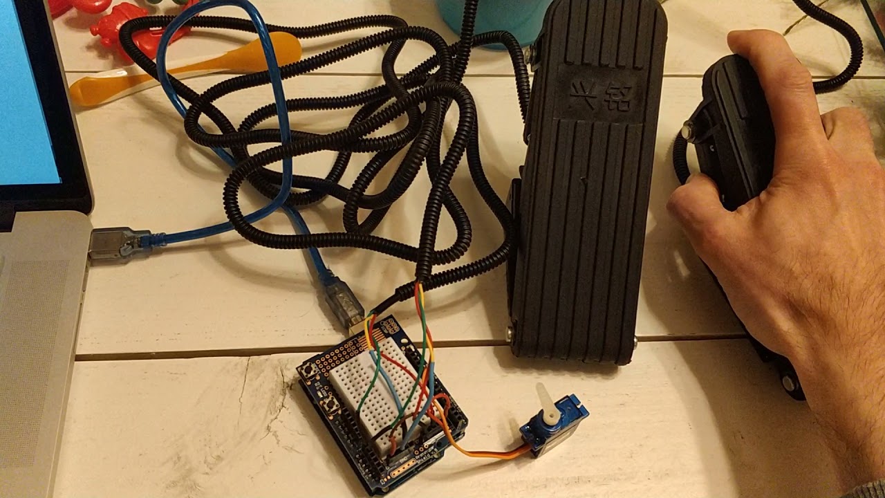
I chose hall sensor pedals as they are cheap. There are potentiometer-based pedals, but those are expensive. I've also tried (and succeeded!) a mechanical solution, using a deconstructed servo tester: RC Throttle & Brake/Reverse pedals - YouTube

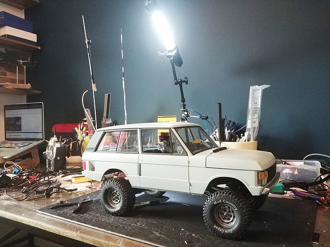
My FPV truck can be seen in action here: Axial SCX10 II FPV - YouTube, whereas it looks like this:

Thanks again, @Railroader. I'll start monitoring the values closer tomorrow. I have the idea that I'm close to the solution but it needs more pondering.

Please do some more investigating and test data collecting. It might be a logic mistake.

Please post a circuit diagram, NOT a Fritzy image.
A hand drawn circuit will be fine.
Please include, power supply, component names and pin labels

There's isn't really a lot to show here I'm afraid. The hall sensors are directly connected to A0 and A1 of the Uno, the PWM signal/servo has D9 as output.

My code works perfectly fine, precise even when using code for one Hall sensor pedal. It either goes the whole range (180 degrees) or 90 degrees in one direction, depending on the mapping numbers.

But having one pedal to control the servo angle 90 to 0 degrees and the other pedal 90 to180 degrees is something not as easy as I thought it would be.

I suggest adding a Serial.print of the result after the mapping also

This is a great idea. Perhaps I can use these angle values for the if - statement. I'll see what I can come up with. :slight_smile:

.

That's the idea for debug printing.
Heja Sverige?

Hi,
Fine on the pedal operations.
So you want FWD PEDAL and a REVERSE BRAKE PEDAL.
You need to have flags in your code to indicate what mode you are in.

If you are in FWD, then a flag to indicate FWD mode, then when you hit the BRAKE pedal, you need to come to a stop, so you will need a flag to indicate the FIRST BRAKE application.

This flag will make sure the next brake application will be REVERSE, or if the next pedal pressed is the FWD, for the vehicle to go forward.

In the real world, I push throttle and brake together after I have gone through water to dry the brakes out.

Thanks.. Tom... :grinning: :+1: :coffee: :australia:
PS, If you really wanted to simulate the real world, you need throttle, brake and gear selector(just for direction or a simulated sequential gearbox).

@Railroader I'm Dutch :slight_smile:

@TomGeorge The whole process of neutral-brake or neutral-forward is already done in the speedcontroller. All it needs is a PWM signal between 1000us-2000us to have the desired effect. There are servo-controlled gearboxes for sale for a RC truck like mine, but then the camera pan-servo wouldn't fit the way I built the truck. I want to do a redo of the whole truck sometime, but time is limited.

BUT...

After a short night sleep (fireworks+baby) I think I almost got it after a fresh dose of caffeine. I saw some code online that used the if - else statement. Never used it before so I was a bit cautious.
And behold, it's working almost like I want to. Forward is somewhat OK for the range of 90 to 135 degrees (why135?, I want 180!). Reverse is a bit on/off. Reverse jumps from 90 to 45, and the last 45 to 0 degrees goes smooth. I think I need to play with the min/max values so there's no overlap that can cause weird behavior.

#include <Servo.h>
#define PwmIN1 9 // Arduino pin for the pwm output1
#define Hall_SensorT A0 // Arduino pin for the Throttle Hall sensor analog input
#define Hall_SensorB A1 // Arduino pin for the Brake Hall sensor analog input
int angle1 = 0;
int Val1 = 0;
int Val2 = 0;

Servo myservo;

void setup() {
  myservo.attach(PwmIN1);
  pinMode(Hall_SensorT, INPUT);
  pinMode(Hall_SensorB, INPUT);
  Serial.begin(9600);
}
void loop() {
  Val1 = analogRead(Hall_SensorT); // read the analog Throttle input
  Val2 = analogRead(Hall_SensorB); // read the analog Brake input

  // Serial.println(Val2); // My Hall sensors measure between 180 min and 850 max values, 515 being the middle

  if ((Val1 >= 516) && (Val1 <= 850))
  {
    angle1 = map(Val1, 180, 850, 90, 170); // from Neutral to Max Brake
    myservo.write(angle1);

  } else if ((Val2 >= 180) && (Val2 <= 515))

    angle1 = map(Val2, 180, 850, 90, 10); // from Neutral to Max Throttle
  myservo.write(angle1);

  //Tested with code for single Hall sensor 180, 850, 90, 10 from Neutral to Max Throttle
  //Tested with code for single Hall sensor 180, 850, 90, 170 from Neutral to Max Brake

  Serial.println(angle1); // ToDo: check the Serial values for angle1 and angle2

}

Also, @TomGeorge, I looked into the Flag-statement, and although I don't understand it yet, I think I see what you mean. I'll try that once I know how to implement it.

Thank you all for not writing code solutions , but directions of how to get there. Having a dead end job, this Arduino stuff has my brain reactivated the last couple of weeks for the first time in years :slight_smile: Now lets see if I can fine tune this into a working piece of art.

...I got it :nerd_face:

This works! Connecting this signal to a PWM-to-PPM converter, connected to the trainer port of an RC radio will be my next step.

#include <Servo.h>
#define PwmIN1 9 // Arduino pin for the pwm output1
#define Hall_SensorT A0 // Arduino pin for the Throttle Hall sensor analog input
#define Hall_SensorB A1 // Arduino pin for the Brake Hall sensor analog input
int angle = 0;
int Val1 = 0;
int Val2 = 0;

Servo myservo;

void setup() {
  myservo.attach(PwmIN1);
  //myservo.writeMicroseconds(1500);
  pinMode(Hall_SensorT, INPUT);
  pinMode(Hall_SensorB, INPUT);
  Serial.begin(9600);
}
void loop() {
  Val1 = analogRead(Hall_SensorT); // read the analog Throttle input
  Val2 = analogRead(Hall_SensorB); // read the analog Brake input

  if  (((Val1 >= 180) && (Val1 <= 850) && (Val2 >= 150) && (Val2 <= 179)))
  {
    angle = map(Val1, 180, 850, 90, 180); // from Neutral to Max Brake
  }
  
  else if (((Val2 >= 180) && (Val2 <= 850) && (Val1 >= 150) && (Val1 <= 179)))
  {
    angle = map(Val2, 180, 850, 90, 0); // from Neutral to Max Throttle
  }

  myservo.write(angle);

  //Tested with code for single Hall sensor 180, 850, 90, 10 from Neutral to Max Throttle
  //Tested with code for single Hall sensor 180, 850, 90, 170 from Neutral to Max Brake

  //Serial.println(Val1);
  //Serial.println(Val2);
  Serial.println(angle);
}

Next step is adding a potentiometer input for steering. But that's easy as it's just a servo tester.

Good. Keep up the wind in the sails.

Hi Hans, any update on getting it connected to the trainer port yet? Im attempting to do something similar with a Futaba transmitter and some arduino libraries for sbus.

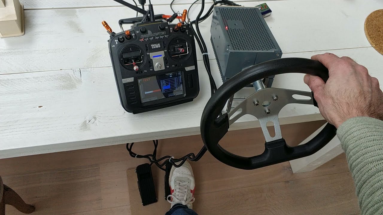
This code is tested for Throttle+brake and steering as input. I haven't tested the headtracking input yet (pan/tilt).

Be aware you still need a PWM-to-PPM converter to get a PPM trainer input signal. I got too busy with life lately and I hope to find time to eliminate the converter and do it all with one Arduino.

//HansPalmboom.nl made this!

#include <Servo.h>
#include <PPMReader.h> // part of code for decoding ppm headtracker signal

byte interruptPin = 3; // Input Pin 3 ppm headtracker signal
byte channelAmount = 8; // part of decoding ppm headtracker signal
PPMReader ppm(interruptPin, channelAmount); // part of decoding ppm headtracker signal

#define PwmOUT1 9 // Arduino pin 9 for the pwm output1 throttle-brake
#define PwmOUT2 10 // Arduino pin 10 for the pwm output2 steering wheel
#define Hall_SensorT A0 // Arduino pin A0 for the Throttle Hall sensor analog input
#define Hall_SensorB A1 // Arduino pin A1 for the Brake Hall sensor analog input
#define SteerW A2 // Arduino pin A2 for the steering wheel potentiometer. In the near future a Hall sensor? Rotary = Expensive!

#define PwmINPAN 8 // Arduino pin for the pwm output PAN
#define PwmINTILT 7 // Arduino pin for the pwm output TILT

int angle = 0;
int anglePAN = 0;  //Pan servo angle
int angleTILT = 0; //Tilt servo angle
int Val1 = 0;
int Val2 = 0;
int Val3 = 0;
int Steering = 0;

Servo myservo1; 
Servo myservo2;
Servo myservo3; 
Servo myservo4;


void setup() {
  myservo1.attach(PwmOUT1);
  myservo2.attach(PwmOUT2);
  myservo3.attach(PwmINPAN);
  myservo4.attach(PwmINTILT);
  pinMode(Hall_SensorT, INPUT);
  pinMode(Hall_SensorB, INPUT);
  pinMode(SteerW, INPUT);
  Serial.begin(9600);
}
void loop() {

  unsigned value7 = ppm.latestValidChannelValue(7, 0); //reading PWM value of PPMchannel 7
  unsigned value8 = ppm.latestValidChannelValue(8, 0); //reading PWM value of PPMchannel 8
  
  anglePAN = map(value7, 1000, 2000, 0, 180); 
  angleTILT = map(value8, 1000, 2000, 0, 180);

  
  Val1 = analogRead(Hall_SensorT); // read the analog Throttle input
  Val2 = analogRead(Hall_SensorB); // read the analog Brake input
  Val3 = analogRead(SteerW); // read the analog Steering potentiometer
  Steering = map(Val3, 0, 940, 0, 180); // mapping the potentiometer value to a 0-180 range 1023

  //Val1 Tested with code for single Hall sensor 180, 850, 90, 10 from Neutral to Max Throttle
  //Val2 Tested with code for single Hall sensor 180, 850, 90, 170 from Neutral to Max Brake

  if  (((Val1 >= 180) && (Val1 <= 850) && (Val2 >= 150) && (Val2 <= 179)))
  {
    angle = map(Val1, 180, 850, 92, 180); // from Neutral to Max Brake
  }

  else if (((Val2 >= 180) && (Val2 <= 850) && (Val1 >= 150) && (Val1 <= 179)))
  {
    angle = map(Val2, 180, 850, 92, 0); // from Neutral to Max Throttle
  }

  myservo1.write(angle); // Arduino Throttle/Brake pin 9 to PWM-to-PPM converter
  myservo2.write(Steering); // Arduino Steering pin 10 to PWM-to-PPM converter
  myservo3.write(anglePAN); // Arduino Pin 8
  myservo4.write(angleTILT); // Arduino Pin 7

  //Serial.println(Val1); // checking the input values when debugging
  //Serial.println(Val2); // checking the input values when debugging
  //Serial.println(Val3); // checking the input values when debugging
  //Serial.println(angle); // checking the output values when debugging
  //Serial.println(Steering); // checking the output values when debugging

}