We had an application requiring a 22 keys matrix keypad. We found no hardware capable of reliably encoding any matrix keypad, while most existing software solutions are incomplete, impose a large burden to the processing unit, require many I/Os, have no detection of multiple keys, do not debounce keys, etc.
We decided to design a reliable hardware solution for all applications requiring matrix keypads. Here are the characteristics of this new hardware solution:
******** KEYPAD MATRIX DECODER HARDWARE **********
The KPD32 is a complete keypad matrix decoder of up to eight columns by four rows.
FEATURES
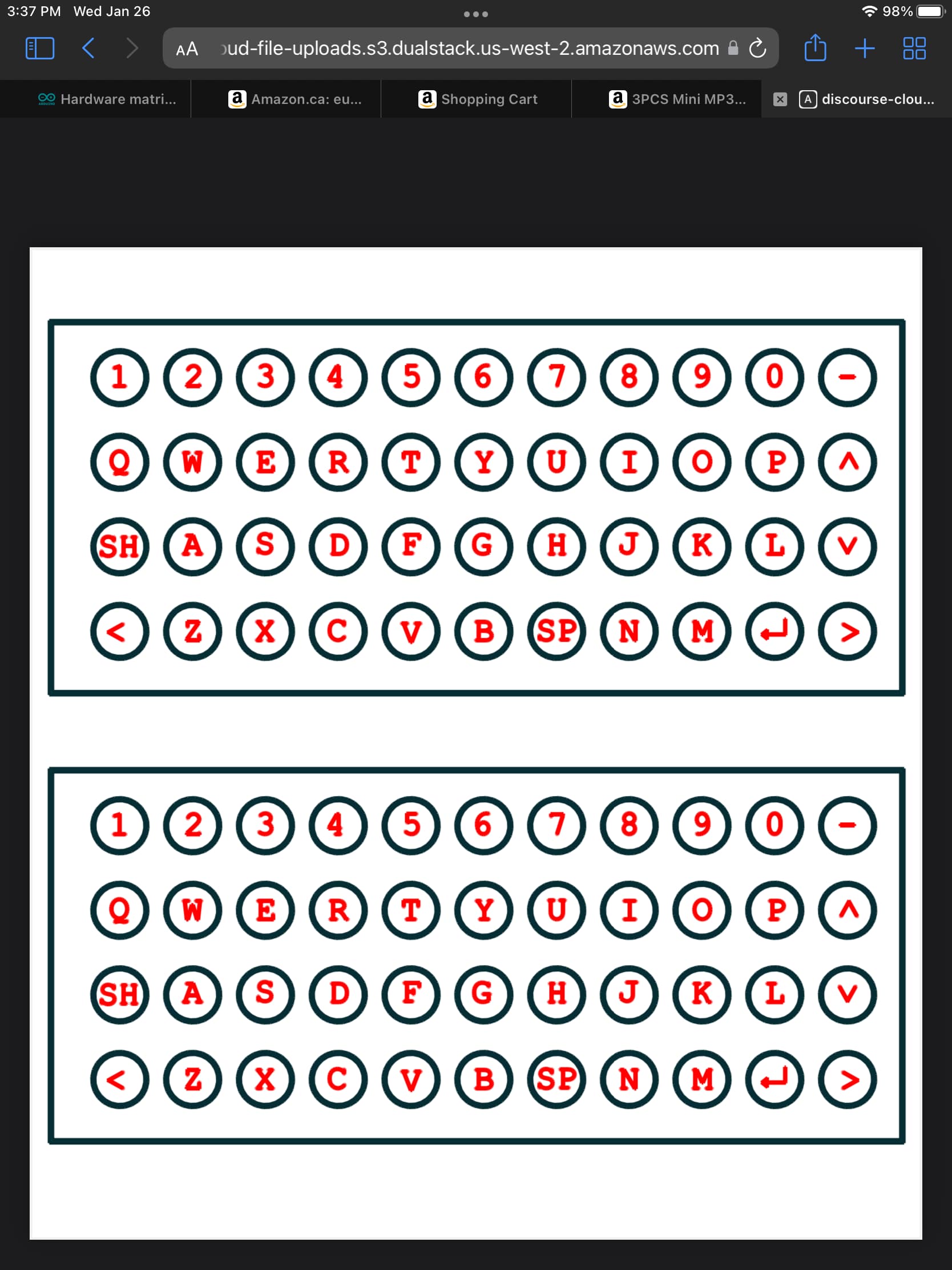
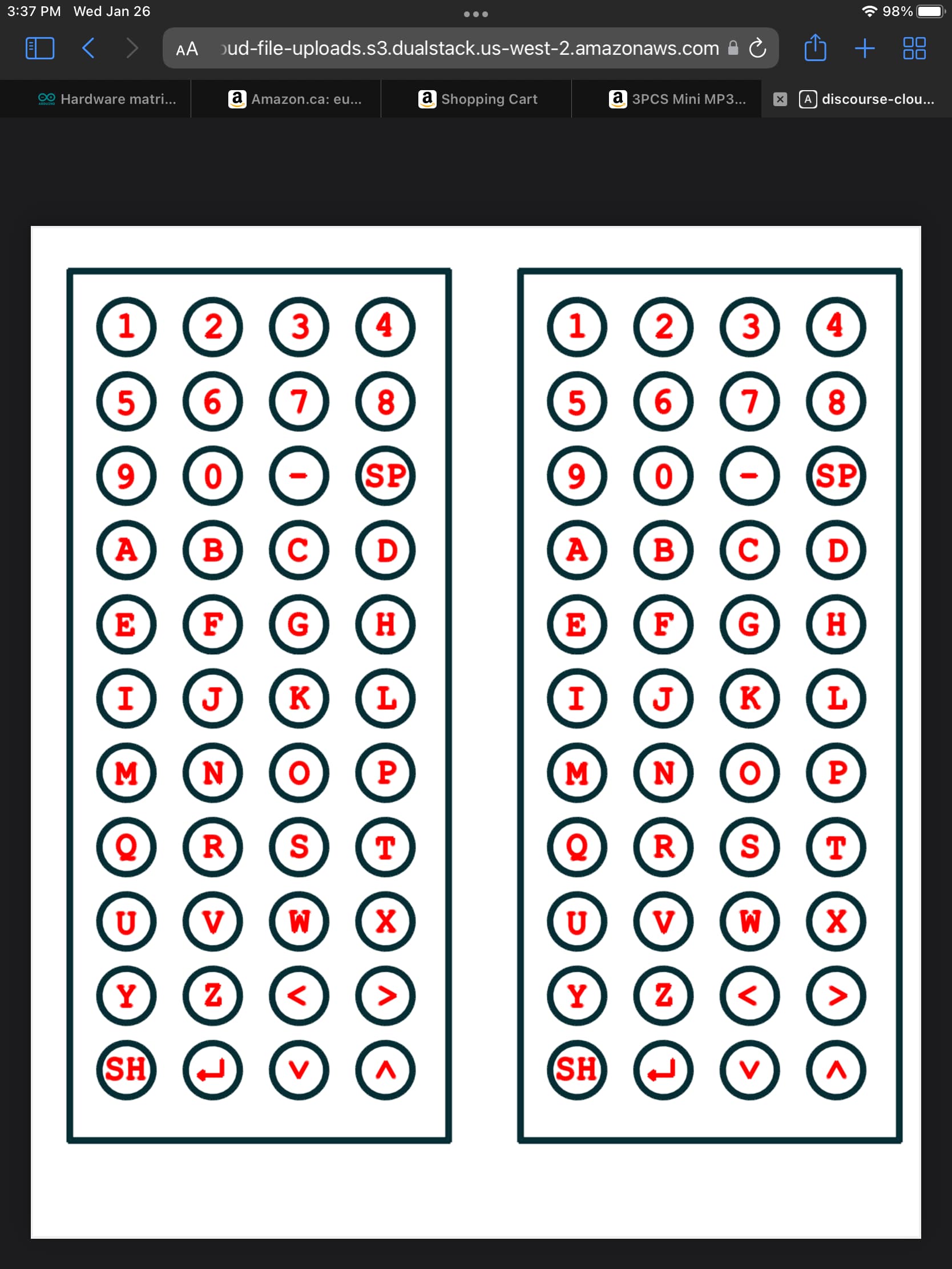
1- Up to 32 matrix keys, 4 rows by 8 columns. (Any smaller configurations (4X3, 4X4, 1X8, etc.) are allowed.)
2- All 32 matrix keys are debounced.
3- Multiple keys detection and rejection. See below.
4- Registered output.
4- SPI compatible interface: SCK, SS (active LOW) and MISO pins allowing serial reading of the decoded keypad.
5- One output pin indicates that a key has been pressed and data is available for reading. (KBAV pin)
6- Completely stand alone: the master unit is relieved from the burden of scanning the matrix, debouncing keys, encoding keys, rejecting multiple keys, etc. The master unit simply polls KBAV for data, and if TRUE, serially reads the decoded data.
7-Two independant keys, not part of the matrix, are read into two bits, and may be used as SHIFT and CONTROL keys. Using these two keys quadruple the codes generated from the keypad matrix: for example 34 keys generate 128 unique codes, 18 keys, 64 codes, etc. The SHFT and CTRL pins are active LO, and have a pull-up resistor on board. Since they are to be pressed before any key in the matrix, there is no need to debounce these keys. Pressing these keys alone do not generate a KBAV status.
MULTIPLE KEYS DETECTION AND REJECTION.
The keypad is hardware-scanned row by row. The central unit is not required for scaning.
A) If two or more keys are simultaneously pressed in the actually scanned row, the lowest column is given priority and this key is encoded, other columns in that row are ignored.
B) When a key has been encoded in a row, all other rows are ignored until all keys in all rows are released. This ensures single key encoding, rejecting any multiple keys cases.
READING SEQUENCE.
Data is transferred LSB first to the master unit , and changes on the negative edge of SCK. Before reading data, the master unit polls KBAV pin for data availability. SCK must is taken low before asserting SS. Then, SS is lowered, starting the reading sequence. The master unit does 8 cycles of single bit reading, each cycle consisting of : a) reading a bit, b)asserting SCK HI, and c) asserting SCK low. The eighth clock resets KBAV. SS should now be taken HI, terminating the reading operation, resetting the reading register, and putting MISO in its tri-state mode allowing for MISO sharing with other modules. In case of overrun (data is not read before a second key is pressed) the first key is retained, and the overrun key is lost.
OUTPUT DATA .
Bit 7 is always zero, bit 6 is the external CTRL key, bit 5 is the external SHFT key, bits 4:3 are the column number where a key has been pressed, and bits 2:0 are the row number where a key has been pressed.
PHYSICAL DATA.
The board measures 2.69" by 1.925" There are two 8 pin headers for connecting the keyboard:
The first header bears COL7:0, the second one bears ROW0:3, SHFT, CTRL, +5V and GND. There are soldering pads for GND, SCK, n.c., MISO, SS and KBAV on one side of the board, and a second set of soldering pads bearing +5v, GND and GND on the other side of the board. The board can be stacked on top of a UNO board, using female headers on the board.