One end of the linkage is fixed and I anticipate calculating the position of the free end based on the encoder readings.The free point will be zeroed before calculating the motion.
First question is, would a single mega board be able to cope with all the interupt processing? It is possible that all 6 encoders would move at the same time.
Or would it be better, for example, to assign a nano to each encoder and network the position back to a controlling Uno?
Depends on how fast the arm is moving. That encoder looks like it has a sinusoidal, differential output, so you will at the very least need a differential-input interface. Also a comparator would be a good idea although it's technically not a requirement.
I use an AM26C32 to convert encoders from differential to single-ended to feed into an arduino or an LS7366 encoder counter if the pulses are too fast (LS7366 can accept encoder pulses at up to 30MHz).
In the case I'm thinking of (I built a device that does this), the arduino could process the signals fast enough. IIRC, the max speed was 3,000 RPM and it is a 4,096 PPR encoder. However, we wanted some "headroom" to add other features so the arduino wasn't spending all its time processing encoder pulses.
Considering the cost of this device, doesn't Heidenhain sell an interface to make reading it easier?
Thanks very much for your reply, you certainly are a lot more knowledgeable than I am.
The differential to signle ended conversion is not something I am familiar with (read:hobbyist)
Also to clarify a couple of variables, the encoder will never make a full revolution, circa 3.5radians maximum. Maximum speed will be circa 200rpm. I presume the forward/reverse sensing will be handled in the code depending on the waveform offset.
One other consideration I have is the number of input lines required at 36 just for the encoders plus I will need an additional 6 for user signalling.
Could I trouble you for a quick scribble on the AM26C32 circuit?
Actually, as I look at the datasheet again, I don't know what I was thinking. That provides two differential, phase-shifted sinusoids over a rotation. It seems like it behaves somewhat like a resolver. Do you have any more data on it?
I think you are correct, it is from a cmm arm circa 1990 that I am trying to ressurect and that phase shift looks like a resolver. They probalby used them due to shock, interference and temperature insensitivity.
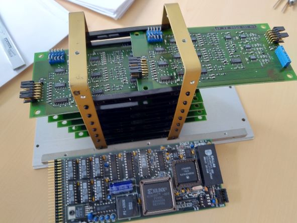
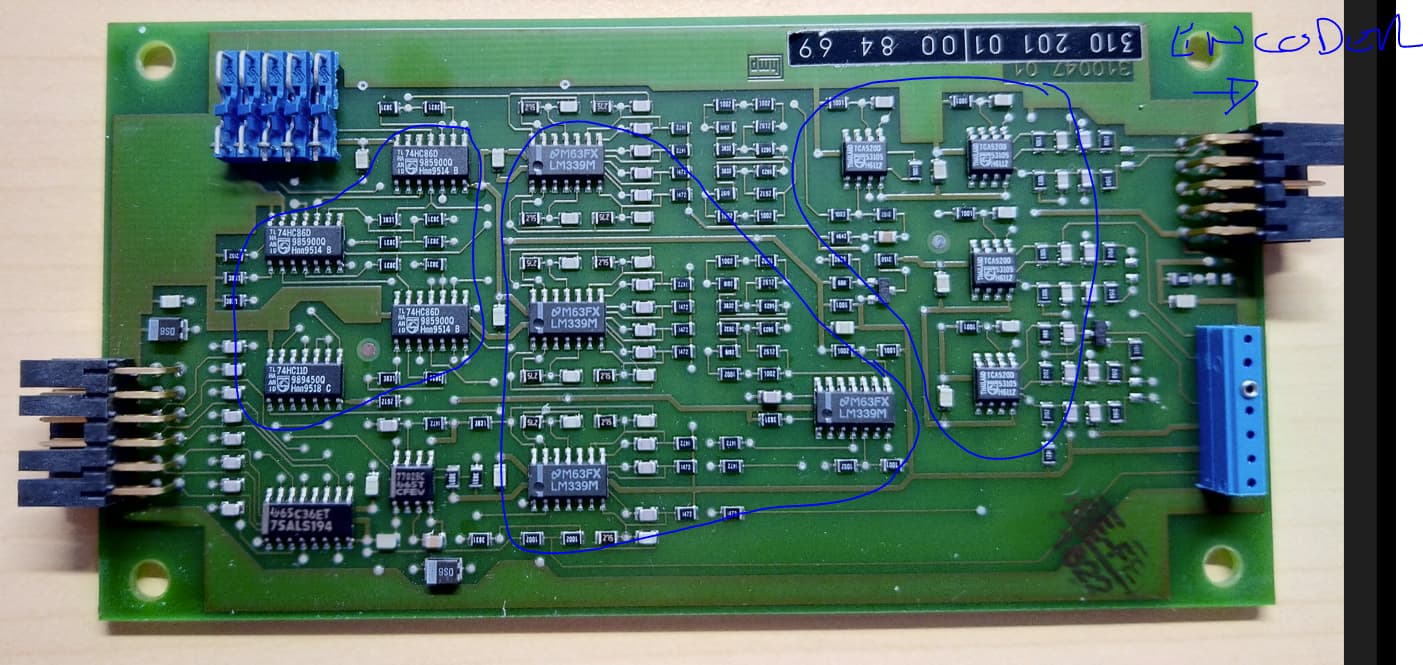
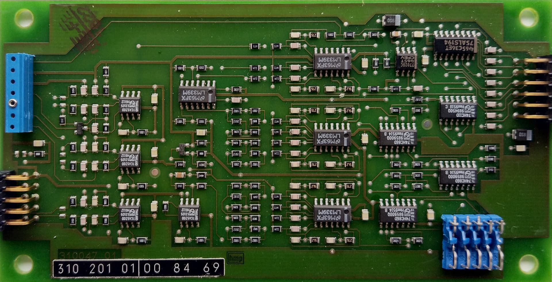
This is the existing circuitry - one board for each axis and a main controller.
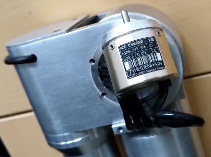
And this is the sensor removed from the joint
I would not know if the A to D coversion is done on the 6 circuit boards or if it would be integral to the sensor but the part number quotes 3600 line counts so it could be the latter
Current output, that's interesting.
Looks like you have some work cut out for you
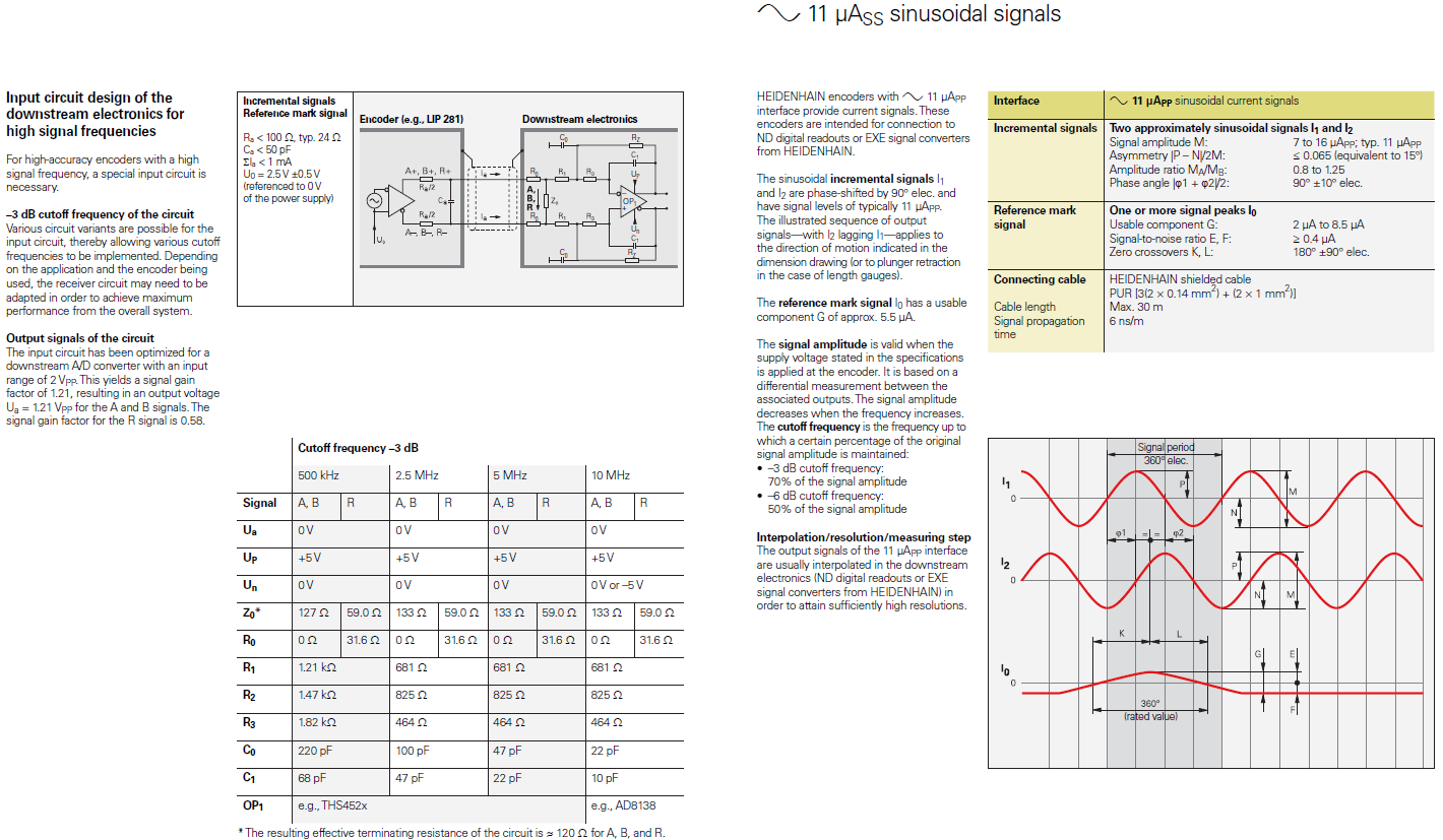
The question I have is that it's not clear whether the sine cycle is from one "line" to the next or it's one cycle over the entire rotation. Heidenhein has a reputation for very high precision measurements, so there's a good chance that it's the former, since it would give the reader the ability to interpolate the position between lines. I haven't ever used one, but I do know that encoders like this exist.
Best way to proceed is probably to put a resistor across one of the output pairs, apply power and watch the voltage across the resistor with a scope. That will give you a good picture of what the output looks like.
Next step would be to build a differential amplifier for each channel using their document as a guide
Might be faster to contact Heidenhein and find out if they still support that encoder and what hardware/software they have that might do what you need.
Hi mate, did that earlier today, was told support ended in 2015 but the guy was helpful, told me it is an optical encoder with a push pull output. It was not a standard item but manufactured with a small firm factor for Romer. Definitely 11 micro amp output
Do you think it would be a good idea to try and create the circuit diagram for the interface board to undertstand what it does and then try and recreate that using more current components? Some of these function may be available as single chip solutions which were not available back in the 90's
Let's take the 30,000 foot view here. Do any of the electronics work? Assuming that the goal is to make the arm usable and not just learn about niche encoders, using the existing interface would probably be the fastest path forward. Then you could read the output TTL signals with an arduino.