Greetings!
Recently, I have been working on a robotics project that involves the use of an HB-25 Parallax Motor Controller. The specifications for this component can be found here.
The main problem I have been running into is the inability to reverse the polarity of the controller.
In order for my robot to function properly, I require the ability to spin the motor forward and reverse, via the controller. The following video shows a successful attempt at programming the Arduino for this functionality:
The HB-25 and Arduino - drbrono
Please note that the HB-25 is being used due to the 6-volt requirement of the DC motor I am using.
Does anyone have the code that would make this work, or would know how to write a program for this task?
I have search countless hours for a solution, but to no avail.
Thank you! 
EDIT:
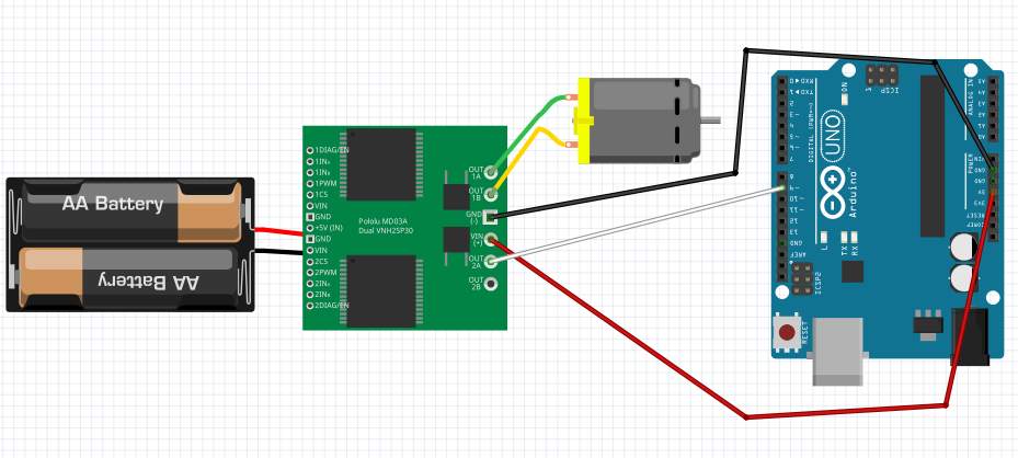
Attached, you will find a circuit diagram and the current program I was testing today.
Please note that the following in the image correspond with each other:
- OUT 1A corresponds with M1 on the HB-25 spec
- OUT 1B corresponds with M2
- GND (-) on the right corresponds with the Servo Ground
- VIN (+) on the right corresponds with the "R", labeled "Not Connected" on the spec
- OUT 2A corresponds with the Servo pulse input
- +5V (IN) on the left corresponds with the 6V input from the external battery to the HB-25
- The black wire from the battery represents ground
Feb06DCMotorTest.ino (1.83 KB)
Hi,
Can you please post a copy of your sketch, using code tags?
Can you please post a copy of your circuit, in CAD or a picture of a hand drawn circuit in jpg, png or pdf?
http://forum.arduino.cc/index.php?topic=187545.0
That will help us answer your questions.
Tom..... 
Hello Tom,
Thank you for the response. I will prepare the necessary items.
Thank you!
First line of the key features in the link you provided........
Pulse Input: 1.0ms Full Reverse, 1.5ms Neutral (off), 2.0ms Full Forward
Looks like the controller takes a servo signal. Try the servo library that comes with the IDE.
bluejets:
First line of the key features in the link you provided........
Pulse Input: 1.0ms Full Reverse, 1.5ms Neutral (off), 2.0ms Full Forward
Hello,
Please note that I am new to working with Arduino programming. I am fully aware of the specs, and I have tried multiple methods for the HB-25 controller, including writeMicroseconds(), which did not work. This caused the motors to constantly pulse at a high rate, rather than move in a clockwise/counterclockwise motion. There was practically no motion.
Thank you.
groundfungus:
Looks like the controller takes a servo signal. Try the servo library that comes with the IDE.
Thank you for your response! I have already tried that, but it has not worked. I will share the code I have written shortly, along with the circuit's setup.
TomGeorge:
Hi,
Can you please post a copy of your sketch, using code tags?
Can you please post a copy of your circuit, in CAD or a picture of a hand drawn circuit in jpg, png or pdf?
HB-25 Motor Controller will not work - Motors, Mechanics, Power and CNC - Arduino Forum
That will help us answer your questions.
Tom.....
Hello again, Tom. I have added the sketch code and a diagram of the circuit. Please reference the bullet points I added with regards to what corresponds with what on the HB-25.
Pulse Input: 1.0ms Full Reverse, 1.5ms Neutral (off), 2.0ms Full Forward
Sane pulse duration as used by servos. Basic servo test code you can use for testing. Try sending values between 45 and 135 from the serial monitor. This uses pin 9 for the servo signal.
//zoomkat 7-30-10 serial servo test
//type servo position 0 to 180 in serial monitor
// Powering a servo from the arduino usually *DOES NOT WORK*.

String readString;
#include <Servo.h>
Servo myservo;  // create servo object to control a servo

void setup() {
  Serial.begin(9600);
  myservo.attach(9);
  Serial.println("servo-test"); // so I can keep track of what is loaded
}

void loop() {

  while (Serial.available()) {
    char c = Serial.read();  //gets one byte from serial buffer
    readString += c; //makes the String readString
    delay(2);  //slow looping to allow buffer to fill with next character
  }

  if (readString.length() >0) {
    Serial.println(readString);  //so you can see the captured String
    int n = readString.toInt();  //convert readString into a number
    myservo.write(n);
    readString="";
  }
}
zoomkat:
Sane pulse duration as used by servos. Basic servo test code you can use for testing. Try sending values between 45 and 135 from the serial monitor. This uses pin 9 for the servo signal.
//zoomkat 7-30-10 serial servo test
//type servo position 0 to 180 in serial monitor
// Powering a servo from the arduino usually DOES NOT WORK.
String readString;
#include <Servo.h>
Servo myservo; // create servo object to control a servo
void setup() {
Serial.begin(9600);
myservo.attach(9);
Serial.println("servo-test"); // so I can keep track of what is loaded
}
void loop() {
while (Serial.available()) {
char c = Serial.read(); //gets one byte from serial buffer
readString += c; //makes the String readString
delay(2); //slow looping to allow buffer to fill with next character
}
if (readString.length() >0) {
Serial.println(readString); //so you can see the captured String
int n = readString.toInt(); //convert readString into a number
myservo.write(n);
readString="";
}
}
Thank you for your assistance! I will have to test out the code tomorrow. I will make an additional reply and/or edit this post if it works.
Thanks again.
Hi, when you add information, can you do it in a new message, editing an old message can confuse anyone who has just read the thread.
Your "diag" is a fritzy which is not a circuit diagram, the board in the diag is not the controller.
Please a picture of your project, and a pic of a hand drawn circuit if possible, showing how you have connected the three wires from the arduino to the driver connector.
Tom...
TomGeorge:
Hi, when you add information, can you do it in a new message, editing an old message can confuse anyone who has just read the thread.
Your "diag" is a fritzy which is not a circuit diagram, the board in the diag is not the controller.
Please a picture of your project, and a pic of a hand drawn circuit if possible, showing how you have connected the three wires from the arduino to the driver connector.
Tom...
Sorry about that, I will take note of that for next time. I will see to taking a picture when I'm in the shop.
Thanks to the basic Servo code that zoomkat provided, I was able to get the motors working!
I first ran some tests by sending input through the Serial Monitor, then I used the same logic to expand my program.
Thank you to all who helped, and a very special thank you to zoomkat!
Hi, good to hear, did you get your code to work as well and what did you find?
Tom.....
TomGeorge:
Hi, good to hear, did you get your code to work as well and what did you find?
Tom.....
Hello,
Yes, I got the code to work by replacing all of the digitalWrite() methods with <servo_name>.write() and entering integer values to control direction and speed.
The following are the results I gathered for integer values entered in the .write():
Clockwise:
50 - max speed
60
70
80 - low speed
Counter-clockwise:
135 - max speed
125
115
105 - low speed
stop:
0