Toshiba TB67H420FTG motor driver reversal problems

Well...it's me again, trying to figure it out. I cannot get my motor driver to reverse the motor. It kills the voltage.

Here is what I have:
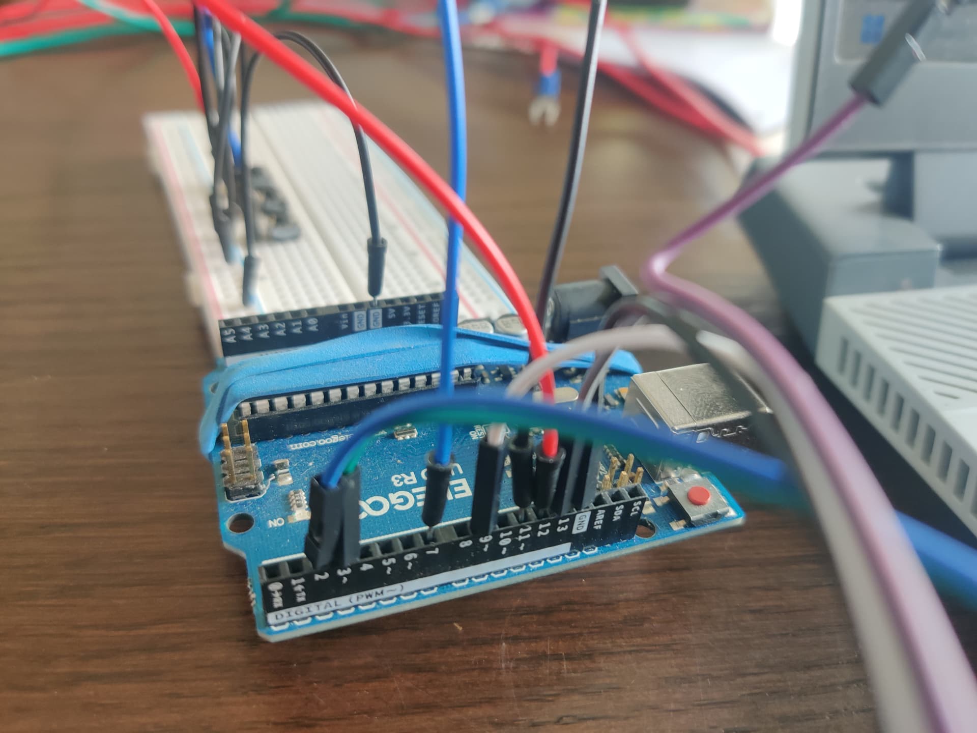
*Arduino UNO
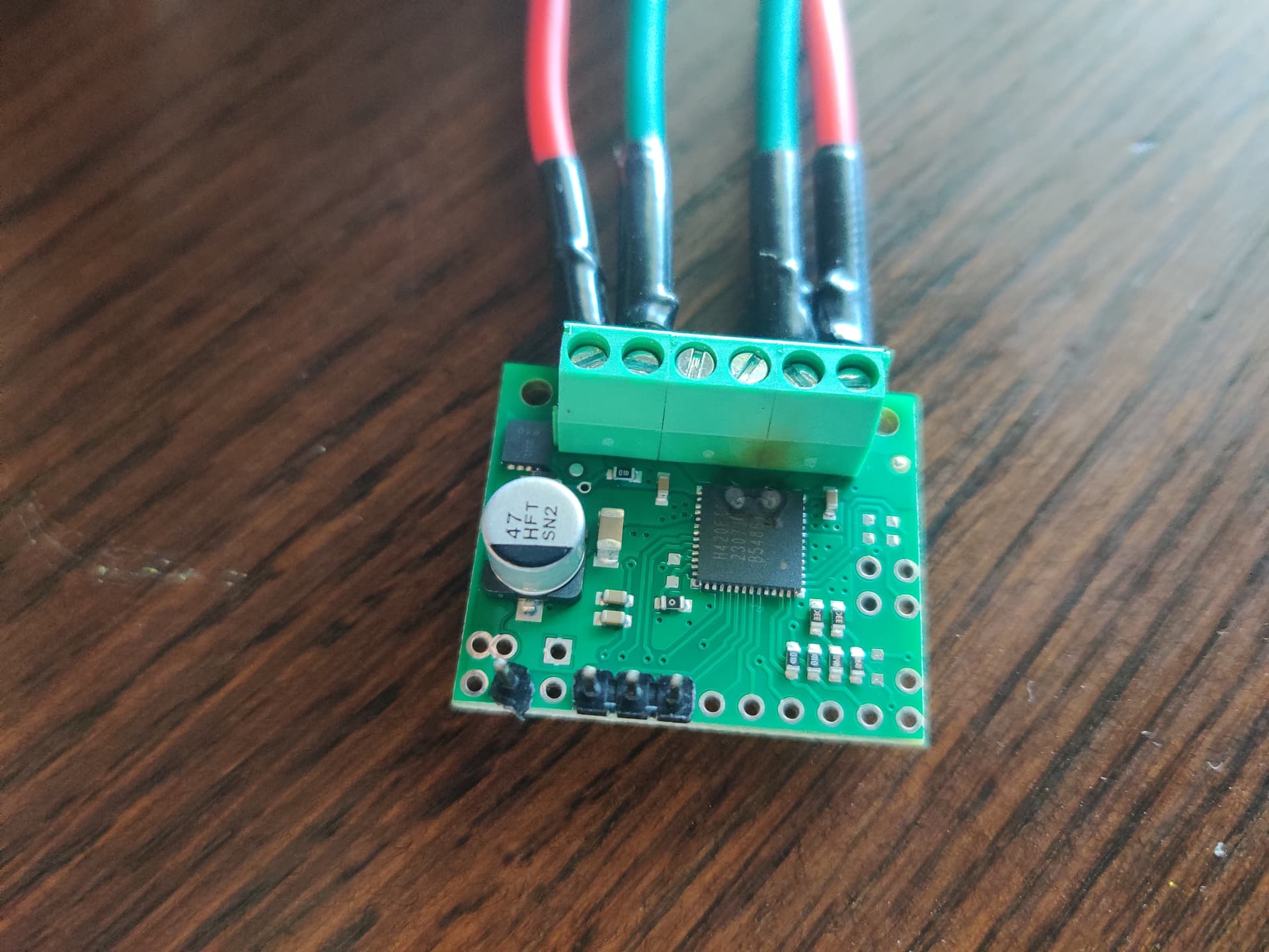
*Toshiba TB67H420FTG mounted on Pololu's module, found here. And this is the specific datasheet.
*9 volt battery for motor power (currently 6 AA batteries in series)
*small DC motor from a starter kit.
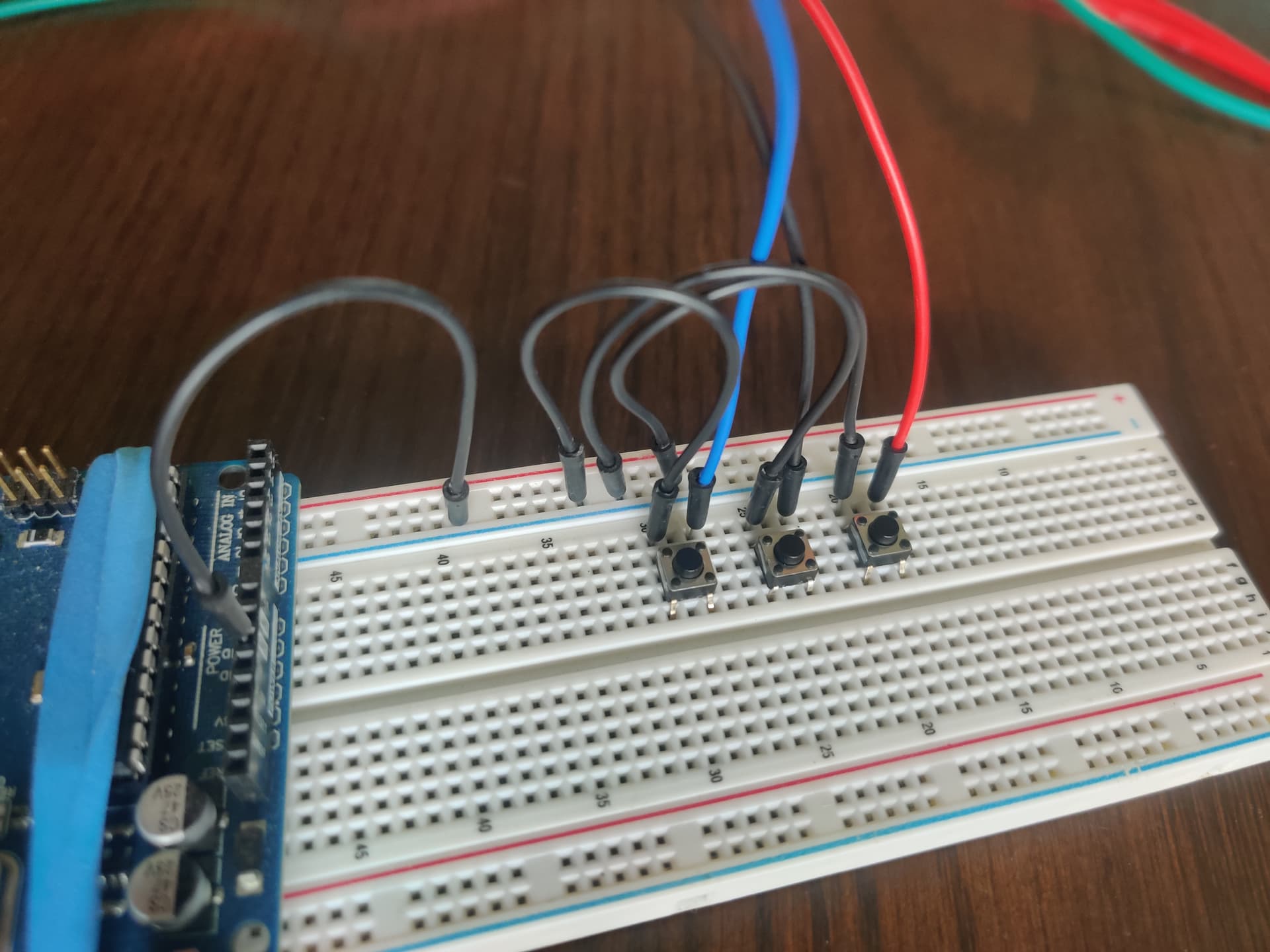
*3 buttons to control it.
--One to enable/disable the motor. Push to enable, release to disable.
--One for direction control. Push for clockwise, release for counter clockwise.
--One for speed control. Push for analog write full speed, release for analog write slow speed.

Here is what I want to happen:
*After startup, push and hold enable button to enable motor in whichever direction the direction button is held or released in, CW or CCW. While the enable button is held and the direction button is held or released, push the speed button for fast speed or release it for slow speed. So all of these buttons are not push once and it stays in that mode, but push it and while it's held do something or release it and while it's released do something different.

Here is what is happening:
*According to the serial prints, the buttons ARE working, or registering HIGH and LOW. So I know the arduino is getting the command from the buttons.
*The enable button does indeed enable while pushed and disable while released.
*The speed button does indeed do slow speed while released and fast while pushed.
*The problem here is the direction button. Everything works flawless in one direction but when I try to reverse the direction, it all stops. I removed the motor and used the multimeter in it's place. It showed that the voltage drops when the direction is changed.
*In CW mode, the slow and fast voltages are .94 and 1.49 while enabled.
*But while enabled and in CCW mode the voltages are correct. Slow is -5 and fast is -8.6.
*And while disabled, all voltages are 0, as it should be.

I want to post some pics and code and was hoping someone show me where I am going wrong. It has to be something simple.

The driver is set up for dual motor, even though I am just controlling one motor for now. I figured that it is no different than hooking up two motors but only telling one of them what to do. Correct me if I am way off base here...

I have the code split into multiple tabs in my ide, but I will get it all posted here. Here is the main code:

//CONTROL MOTOR WITH POLOLU TB67H420FTG MOTOR DRIVER
//For dual or single motors

/*-----FORMULAS----------------------------------------------
---Current sensing---Per Toshiba TB67H420FTG datasheet pg13
---NEEDS MORE RESEARCH TO CONTROL CURRENT!!!

If HBMODE == HIGH (Driver is in single channel mode)
     Iout=Vref * 2.5

If HBMODE == LOW (Driver is in dual channel mode)
     motorA current = Iout=Vref * 1.25
     motorB current = Iout=Vref * 1.25
     
*/

/*-----Wiring------------------------------------------------
---Power to board is supplied via 10V to 47V VIN pin.
---GROUND THE BOARD!
*/

// Declare other .ino tab codes
void motor1Stop();
void motor1CW();
void motor1CCW();
void motor2Stop();
void motor2CW();
void motor2CCW();

//-----DEFINES-----------------------------------------------

//Button inputs
#define PUSHED      LOW
#define RELEASED    HIGH

//Motor Speed
#define FAST        255
#define SLOW        150

//-----PIN ASSIGNMENTS---------------------------------------

//Motor control
const int motor1SpeedPin = 9;                     // Primary PWM pin
const int motor2SpeedPin = 10;                    //Secondary PWM pin
int motorSpeed;                                   //Two choices, FAST or SLOW

const int motor1CWPin = 3;                        //Direction control motor1
const int motor1CCWPin = 2;                       // Direction control motor2
const int motor2CWPin = 5;                        //Direction control motor2
const int motor2CCWPin = 6;                       //Direction control motor2

//Buttons/Switches
const int enableButtonPin = 7;                    // Motor enable button
const int directionButtonPin = 11;                // Direction control button
const int motorSpeedPin = 12;                     //push button for fast speed, release for slow speed

//Current sensing pins---Writes data TO the motor controller.
const int motor1Sensor = A0;                      //Write analog voltage to VrefA
const int motor2Sensor = A1;                      //Write analog voltage to VrefB

//-----MOTOR DRIVER SETUP--------------------------------------
const int HBMODE = 13;                            //In SETUP, set to HIGH for single motor, LOW for dual motor
bool isSingle = true;                             //Is driver in single or dual mode?

//-----TIMERS---------------------------------------------------
unsigned long lastCheckTime = 0;                  //Check debounce timers
const int debounceDelay = 50;                     //50 mS debounce delay
unsigned long lastSpeedTime = 0;                  //Keep track of speed button
unsigned long lastEnableTime = 0;                 //Keep track of enable button
unsigned long lastDirectionTime = 0;              //Keep track of direction button

//-----BOOLEANS-------------------------------------------------
bool isEnabled = true;                            //Is the enable button pushed?
//bool isDisabled = false;                        //Is the enable button released? Probably not needed. I can assume if it is not enabled, it is disabled.
bool isCW = false;                                //Is the direction button pushed?
//bool isCCW = true;                              //Is the direction button pushed? Probably not needed. I can assume if it is not CW, it is CCW.        

//---E N D  O F  V A R I A B L E S-------------------------------

void setup() {

  Serial.begin(9600);

  // Motor control pin modes
  pinMode(motor1SpeedPin, OUTPUT);
  pinMode(motor2SpeedPin, OUTPUT);

  pinMode(motor1CWPin, OUTPUT);
  pinMode(motor1CCWPin, OUTPUT);

  pinMode(motor2CWPin, OUTPUT);
  pinMode(motor2CCWPin, OUTPUT);

  // Button control pin modes
  pinMode(enableButtonPin, INPUT_PULLUP);              //digital read LOW (PUSHED) to enable
  pinMode(directionButtonPin, INPUT_PULLUP);           //digital read LOW (PUSHED) for CCW and HIGH (RELEASED) for CW
  pinMode(motorSpeedPin, INPUT_PULLUP);                //digital read LOW (PUSHED) for FAST speed and HIGH (RELEASED) for SLOW speed

  // Start with motor off
  analogWrite(motor1SpeedPin, 0);
  analogWrite(motor2SpeedPin, 0);

  // Setup HBMODE for single or dual motor. 
  //IF CHANGING # OF MOTORS, change HIGH to LOW and change isSingle to false.
  pinMode(HBMODE, OUTPUT);
  digitalWrite(HBMODE, LOW);                           //Change to LOW for dual motor, HIGH for single motor with extra current
  isSingle = false;                                    //Change to false for dual motor, true for single configuration

  // Setup Booleans
  isEnabled = false;                                   //Start program with button released
  isCW = true;                                         //Start program with button released


}//---E N D  O F  S E T U P-----------------------------------------

void loop() {

//---CHECK MOTOR SPEED BUTTON-----
if (millis() - lastSpeedTime >= debounceDelay){             //Debounce timing
     if (digitalRead(motorSpeedPin) == PUSHED){             //Is button pushed?

          motorSpeed = FAST;                                //Run motor(s) fast
          lastSpeedTime = millis();                         //Reset timer

     }

     else {                                                 //Is button released?

          motorSpeed = SLOW;                                //Run motor(s) slow
          lastSpeedTime = millis();

     }
}

 
//---CHECK ENABLE BUTTON-----
if (millis() - lastEnableTime >= debounceDelay){             //Debounce timing
     if (digitalRead(enableButtonPin) == PUSHED){            //Is button pushed?

          isEnabled = true;                                  //Set enabled
          lastEnableTime = millis();                         //Reset timer

     }

     else{                                                   //Is button released?

          isEnabled = false;                                 //Set disabled
          lastEnableTime = millis();                         //Reset timer

     }
}

//---CHECK DIRECTION BUTTON-----
if (millis() - lastDirectionTime >= debounceDelay){          //Debounce timing
     if (digitalRead(directionButtonPin) == PUSHED){         //Is button pushed?

          isCW = false;                                      //If pushed, set for CCW
          lastDirectionTime = millis();                      //Reset timer

     }

     else{                                                   //Is button released?

          isCW = true;                                       //If released, set for CW
          lastDirectionTime = millis();                      //Reset timer
          
     }
}

//---DISABLE MOTOR(S)-----
if (isEnabled == false){                                     //Is enable button released?

     motor1Stop();
     motor2Stop();

}

//---RUN MOTOR(S)-----
if (isEnabled == true){                                      //Is enable button pushed?

     analogWrite(motor1SpeedPin, motorSpeed);                //turn on motor1
     analogWrite(motor2SpeedPin, motorSpeed);                //turn on motor2

     if(isCW == true){                                       //Is direction button released?

          motor1CW();
          motor2CW();

     }
     else {                                                 //Is direction button pushed?

          motor1CCW();
          motor2CCW();

     }
}

/*Serial.print("EnButton= ");
Serial.print(digitalRead(enableButtonPin));
Serial.print("  SpeedButton= ");
Serial.print(digitalRead(motorSpeedPin));
Serial.print("  DirButton= ");
Serial.print(digitalRead(directionButtonPin));

Serial.print("  isEnabled= ");
Serial.println(isEnabled);*/

}//---E N D  O F  L O O P-------------------------------------------


Here is the motor control code:

void motor1CW(){

digitalWrite(motor1CWPin,HIGH);
digitalWrite(motor1CCWPin,LOW);

}
void motor1CCW(){

digitalWrite(motor1CWPin,LOW);
digitalWrite(motor1CCWPin,HIGH);

}
void motor1Stop(){

     analogWrite(motor1SpeedPin, 0);
     digitalWrite(motor1CWPin,LOW);
     digitalWrite(motor1CCWPin,LOW);

}
void motor2CW(){

digitalWrite(motor2CWPin,HIGH);
digitalWrite(motor2CCWPin,LOW);

}
void motor2CCW(){

digitalWrite(motor2CWPin,LOW);
digitalWrite(motor2CCWPin,HIGH);

}
void motor2Stop(){

     analogWrite(motor2SpeedPin, 0);
     digitalWrite(motor2CWPin,LOW);
     digitalWrite(motor2CCWPin,LOW);

}

Here are some pics of wiring and my hand drawn "schematic":


Any ideas? I know someone will see something I am missing. Thanks.

1 Like

Thanks for the links. However the central circuit is one matter and the board connectors is a different one.

Please post schematics showing the connectors/pins designations. Pen and paper is okey.

What voltage is dropping?

I hope You don't run full speed and then change direction. That might overload the driver and it shuts down.

1 Like

Are you referring to inputs and outputs? Or where it actually leads to on the driver chip? Can you clarify for the newb?

The voltage going to the motor leads out of the motor driver board. In one direction, CW, the motor leads are only getting low voltages to them, not near enough to power the motor. In the opposite direction, CCW, the motor leads are getting plenty of voltage to them. It runs great in that direction.

As a side note I did measure the input voltage on the logic input side of the driver. As expected, when the enable button is pushed, that pin goes from 0 volts if not pushed to a lower (2.6ish) or higher (5ish) volts, depending on if the speed button is pushed or not while the enable button is pushed. And the direction pins each switch form 0 volts or 5 volts, depending on if the direction button is pushed. So that is all good there on that side. It seems as if the code works correctly, but I am scratching my head.

That was a consideration when I started. I never did attempt to run it full speed and then immediately reverse it. At one point I had it coded with a pause using the stopMotor() for about 150 milliseconds (using millis() timer, not delay). For example, when the button was pushed, stop the motor for 150 milliseconds, and then resume power in the direction the button said to go. The same for if the button was released, briefly stop, then power up in the direction the button said to go. But that wasn't working at all. It would not enable the motor at all.

I then removed the "stop motor briefly" code just to see if I could get it to run at all. That is when the enable button and speed button started working, but not the direction button. At that point, realizing I had an issue and not wanting to damage anything, I unhooked the motor and started using the multimeter in it's place. That is when I noticed the voltage difference to the motor leads depending on motor direction.

EDITED:
I do have another identical motor driver from Pololu. I bought two of them. I could try the other board and see if it works. But I feel like it has to be a configuration of some sort.

1 Like

Summing all up: A complete schematics for boards and buttons is requested.

and power of all pins involved between driver, controller and power sources.
For the board and the controller,

Okey.

Sounds like a code and wiring issue.

1 Like

Here is a schematic for the motor driver board:

And here is the schematic for the uno from the arduino website:
Arduino_UNO_R3-schematics.pdf (69.9 KB)

It saved as a .pdf file.

Do these help?

As far as the buttons, they are all ran from the arduino pins 7, 11, and12 on one side and grounded on the other side. They are all set as INPUT_PULLUP in the setup. The serial prints show that the buttons do work.

I may not have been clear earlier. I am not sure this is worrying. Because this is tested at the enable input pin PWMA on the motor driver module. It measures 0 when it is digitalWrite LOW or analogWrite 0. At analogWrite slow speed (150), it measures about 2.9 (I said 2.6 earlier, my mistake) volts (being PWMed) and at analogWrite fast speed (255) it measures at 5 volts (being PWMed). That is how that pin should behave with those parameters.

See if this will work. These are all measured with the multimeter, nothing is assumed:

The motor direction pins, INA1 and INA2 are both zero if the enable button is disabled. If the enable button is enabled the INA1 and INA2 pins each measure 0 or 5 volts (one is the opposite of the other), depending on if the direction button is pushed or released. This is how it should work. At least with other motor drivers this is how it should work. I think...

The motor enable (PWMA) pin is either 0, 2.9 (I said 2.6 earlier but was wrong), or 5 volts. The 0 volts comes from releasing the enable button. This is correct. If the enable button is released, the motor is disabled with an analogWrite 0. If the enable button is pushed, the PWMA value of 2.9 or 5 volts is due to the motor speed button being released or pushed.

I think the buttons are working correctly. And I also think the buttons are getting the correct data to the motor driver module. I think it is something to do with the motor driver. I am not sure if I have something configured wrong or if it is this driver/module itself. It works in the CCW mode, but the CW mode drives the voltage down to .8 or 1.23 volts, depending on the motor speed button.

Does any of this info help? Thanks again.

1 Like

You have presented everything requested, even more. I'd say @Railroader wanted to see schematics or diagram how everything was wired up, and you went beyond that :+1:

I did have a looksie at the Pololu page and the specs, and one thing stood out:

Minimum operating voltage: 10 V

What if you would use a 12 V PSU? Also check what motor you got, the driver works with brushless DC or stepper motors.

I am betting a motor from a starter kit is neither a brushless DC motor nor a stepper motor!

At the start I was using a fully charged 12 volt lead and battery and getting similar results and problems. It was taking up to much room on the kitchen table so I swapped to the battery pack. But that is a good point. I dropped the ball on that. I will swap back to that battery and quit using the smaller battery pack. Let me get back from work tonight and hook the larger battery back up. I can then post the exact voltages of everything using that battery.

From the item page of Pololu where I bought it: "The TB67H420FTG from Toshiba is an H-bridge motor driver IC that can be used for bidirectional control of one or two brushed DC motors"

And this is from the datasheet in the very first paragraph: "The internal H-bridge can be
controlled independently, as a two brushed DC motor driver"

There IS some conflicting or misleading info about single motor use. The way I read it the datasheet does indicate that if using in single mode (not operating one motor while in dual channel mode, but actually setting it to single channel mode) it operates single stepping motors. Pololu does not specify, only stating it will run one or two DC motors.

I am trying to get one brushed motor to operate correctly while in dual channel mode (should be brushed dc motor mode), then I will add another motor later.

No doubt! But the way I read it, my motor should be fine.

You're correct, I'm sorry.

Hm, if you switch the INA and the motor + -, will the problem also shift? If so that would indicate a problem with the code.

Ok I hooked the 12 volt battery back up and used the multimeter. I got very similar results, just higher voltages:

Battery voltage = 12.45 volts
CCW = -7.3 in SLOW speed, -12.42 in FAST speed
CW =0 in both speeds

Enable in both directions 2.99 and 5.1, depending on speed button
IN1 and IN2 = 0 or 5.1, depending on direction.

So once again, the voltages are getting to the motor driver.

But there is this...

I did switch the INA pins and the problem switched. I have looked my code up and down and backwards and forwards for two days. I am just not seeing the problem. It has to be a bracket or parenthesis or something like that. I am going to take a look again. It is a short code. If I don't find anything I might just rewrite it.

Could be a bad pin on the Arduino as well.. and check that ground have minimal resistance.

Hi, @scottcalv

Looking at your large code you posted at the start of this thread and the fault you have, it looks like you have written a huge lump of code then tried to get it to work.

PLEASE forget your code for the moment, go back to basic code writing.
Write some code that JUST makes your motor go FWD, STOP, REV, STOP and keeps cycling, forget about inputs, just concentrate on CONTROLLING ONE MOTOR with some simple code.

Lets prove you can basically control ONE motor.
Sorry, but I have seen so many massive codes written, and over 100 posts to try and fix it, when starting with simple basic coding would have made a diference.

Write code for each bit of hardware , separately, and get it working then one piece of code at a time put them together and get them working.

Tom.... :smiley: :+1: :coffee: :australia:

1 Like

That will be my next step. I will work on it after work tonight. Thanks.

Here it is:


//-----PIN ASSIGNMENTS---------------------------------------

//Motor control
const int motor1SpeedPin = 9;                     // Primary PWM pin

const int motor1CWPin = 5;                        //Direction control motor1
const int motor1CCWPin = 4;                       // Direction control motor2


//---E N D  O F  V A R I A B L E S-------------------------------

void setup() {

  Serial.begin(9600);

  // Motor control pin modes
  pinMode(motor1SpeedPin, OUTPUT);
  
  pinMode(motor1CWPin, OUTPUT);
  pinMode(motor1CCWPin, OUTPUT);


}//---E N D  O F  S E T U P-----------------------------------------

void loop() {

delay(2000);

digitalWrite(motor1SpeedPin,HIGH);
digitalWrite(motor1CWPin,HIGH);
digitalWrite(motor1CCWPin,LOW);

delay(2000);

digitalWrite(motor1SpeedPin,LOW);
digitalWrite(motor1CWPin,LOW);
digitalWrite(motor1CCWPin,LOW);

delay(2000);

digitalWrite(motor1SpeedPin,HIGH);
digitalWrite(motor1CWPin,LOW);
digitalWrite(motor1CCWPin,HIGH);

}//---E N D  O F  L O O P-------------------------------------------


New day, new code, same problems. I even moved pins on the arduino to other places. It all gives the same results. I am going to try my other motor driver I bought. It is the same module from the same vendor. Either I do not have something configured correctly, or this is a bum driver.

EDITED: Well I see I forgot to delete the serial monitor out of the new setup code. Since posting this I went back and deleted it out of the code and I still get the same results. It has to be something with the driver...

UPDATE:

It is the driver. I changed the driver. It works fine with a simple CW Stop CCW Stop code. on the multimeter and the motor. Sorry to waste your time. I should have tried that first. Lesson learned. I guess I will get ahold of Pololu.

Moving on from here! Thanks folks.

EDITED: Well it's about 30 minutes later. Everything was going well with my little starter kit motor. And then all of a sudden POP and smoke on the second driver. It actually lit up a little. As you know, when you let the smoke out, you can't arrange it correctly back inside the chip! So now I have a bad driver and a REAL BAD driver! Not sure why that little motor smoked the chip though.

Anyway this gives me an excuse to get some different drivers to play with. Thanks again for the help!

1 Like

Hi,
Can you please post some images of your smoked project?
So we can see your component layout.

Tom.... :smiley: :+1: :coffee: :australia:

Does the drives have some built-in protections?

I can't do much as it's mostly disassembled. There are quite a few pics up above though. But here is the board:

And here is the little motor with a pencil beside it.

It was running good for about 30 seconds, then stopped very briefly, then smoked the board. At the same time it popped, it blue screen of deathed my computer. The motor is not fried. It still spins smooth by hand and runs great when connected directly to a battery.

It is supposed to start "chopping" the amperage at a certain preprogrammed threshold. I am not sure what that means exactly. And these ratings are from the vendor's website (and the datasheet) "up to 1.7 A continuous (4.5 A peak) per motor in dual-channel mode."

In reality it was actually in reverse order, but it happend so fast it was impossible to notice. Theory 1.

Theory 2, the brushes broke down and shorted (>4.5 A) the driver for a brief moment.

My theories are likely also in reverse order.