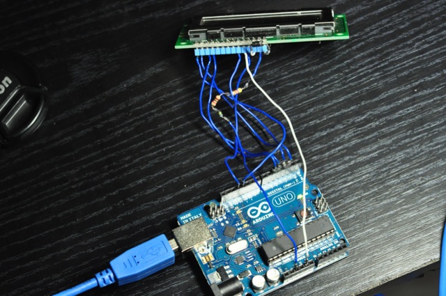
Hi, I'm new to the arduino and this community, I found one of these screens and I was trying to follow this tutorial http://arduino.cc/en/Tutorial/LiquidCrystal but all I get are these weird characters you can see in the attached images.
Instead of using a potentiometer for the contrast setting you could use a diode and a 10K resistor. From pin 3 of the display put a diode (1N4001) to ground (pin 1 of the display). Ring on the diode should be oriented to ground! And put the 10K resistor from pin 2 (Vcc) of the display to 5V supply voltage. On several displays this gives a perfect contrast. If not then use the above mentioned 10K potentiometer. Why this is working: Measuring the voltage at the diode will give 0,65 V. And this is exactly the optimum for contrast on most displays.
I tried using others than the standard lcd library on 0022 with no luck (I'm using an arduino uno).
I also tried adding delays in several parts of the sketch, now I can see those characters better and not so dim, but the problem remains the same. I even tried powering the screen with 3 and 4 AA batteries but it was the same.
Can you see anything wrong with the wiring?
I didn't have a 10k resistor so I used three in series which add up 10k, the diode is a 1N4007
Your pictures are very small and didn't show well which pin is connected to which pin. Suggest you get better pictures. Plus, please use a potentiometer.
It's not the same. You didn't ground pin 1 and the tutorial did. Plus, why did you connect VDD or lcd pin 2 to 3.3V on arduino and had those resistors in series. Which part of that adafruit tutorial told you to do that?
I can't follow that tutorial in it's entirety because I don't have a 10k pot yet, what I meant was that the tutorial on arduino.cc and the one on adafruit is the same, and I followed those except for the part I quoted on my first post, found here http://www.arduino.cc/playground/Code/LCDpot (or not found there, they removed that page sometime between sunday and today...)
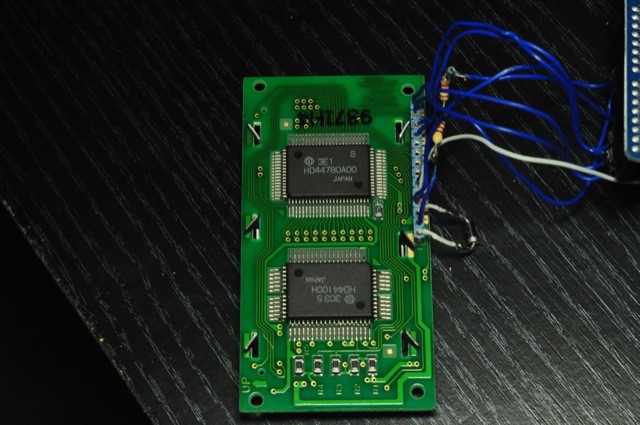
lcd pin 2 is on 5v on the photos, check photo #2 please.
Got it. Remove them, connect lcd pin 2 directly to 5V. Also connect lcd pin 1 to gnd. Get a 10K potentiometer or limp on with the diode (OK for now). You have NOT followed closely to either tutorial, cause both said exactly what I just typed up.
Of course I haven't, I mentioned on my first post that I didn't have a potentiometer so it's impossible to follow those tutorials to the letter, but I quoted that part from arduino.cc where I found an 'alternative' circuit.
I'll get a 10k pot and try that eventually, if that's the only thing you think is wrong with the circuit then thank you for taking a look. I'll update this thread whether I'm successful or not when I get a chance to test it.
Besides the potentiometer, lcd pin 1 needs to be grounded. lcd pin 2 to 5V directly instead of resistors. That's 3 times I said it. Why can't you read my replies.
Yes, same reason, you don't know. I asked you several times why there are several resistors on lcd pin 2 and you still have not answered me why. They should not be there. That is the answer. But I don't think you agree with this answer. You think you did everything correctly and according to the tutorial but you were wrong. Besides, the ground was not connected and you used a half-baked, now-evaporated tutorial instead of getting the potentiometer (I believe this part you start to agree with me now).
You came to the forum seeking answers but you are not willing to admit your mistake(s) and accept the answers. That is why I see the smart-ass answer you provided, "I (OP) don't know, you (you mean me) should ask yourself". So thank you very little for being an ass disregarding my help and hope you have a very self-centered day on the mill.
Your link is bad. Oops - I see that you spotted this too (or maybe you typed it wrong for your post - try looking in your browser history and see if you can verify that what you posted here is what you looked at originally)
I saw that tutorial, it's not there anymore, but you can see it with google cache:
I tried this link and it doesn't work. I get: "Oops... there's nothing to see here. Either you do not have access to these photos, or they don't exist at this web address. Please contact the owner directly to gain access."
what I meant was that the tutorial on arduino.cc and the one on adafruit is the same,
The only thing that is the same about these two tutorials is the sketch that is used. The tutorial on the Arduino page is sketchy at best while the Adafruit tutorial takes you through the process step by step.
I suggest that you disconnect everything and start again. First connect pin 1 directly to GND, connect pin 2 directly to 5v and if you don't have a pot try (a) connecting pin 3 directly to ground or (b) connecting pin 3 to ground via the diode as you did before. At this point you have not connected any data lines or run any sketches. You should have the display shown about halfway through the Adafruit tutorial, just before the 'Bus Wiring' section (except their picture is upside down). Don't continue until you have the single row of black boxes.
Floresta, I hope you get your message through as I tried the same suggestions (pin 1, pin 3, pot) several times and you see what happened on the other end, nothing or less. Picture he showed off-site were decent quality so I pinned down the mistakes but I think he took it off line. I gave up already.
I might just make a video tutorial. There are many things that don't get emphasized over a text/pic based tutorial with nowadays reading habits. Could save so time and grief.