I want to make a clapperboard that can start an Arduino timer wirelessly. A timer has to switch relays in a specific time. These "relays" will switch devices like lighting, effects, cameras. I attached a photo about my idea. My problem is I don't really know how to program Arduinos. Earlier I worked with NRF24 modules for a wireless timing gate which was worked well. If you have any better idea for how to make this, please tell me.
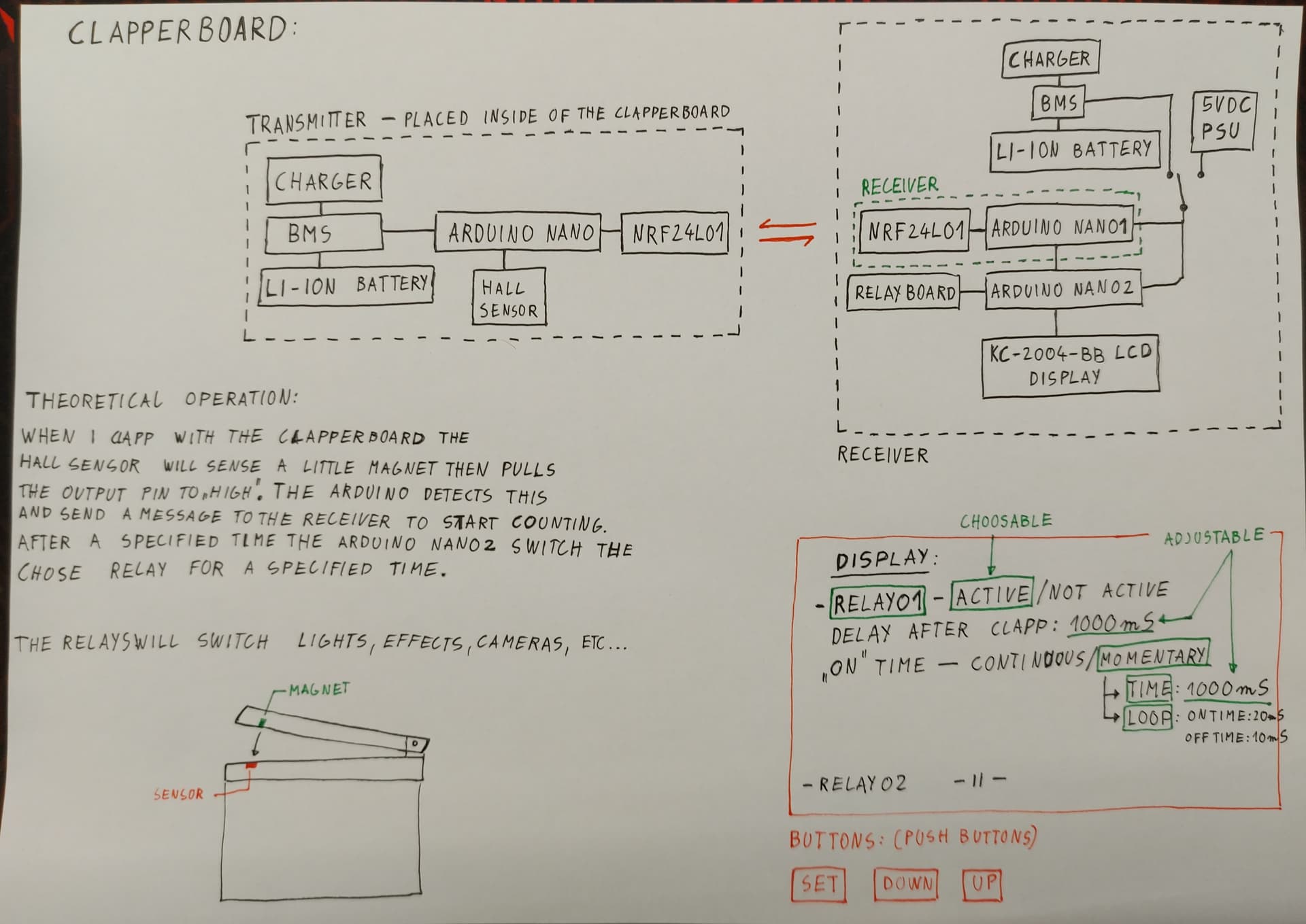
On the photo I've drawn an LCD display which can show me how much time delay I want to set for the relays after "START" = CLAPPING. We can choose between the relays for which one should be active or not active. We can adjust the time or select continuous/momentary "on time" for the relay. For this display I've chosen the KC-2004-BB. It has 20x4 characters.
Theoretical working:
There is a hall sensor, or switch in the clapperboard "not moving part". When the moving part pushes the switch then one of the switch pins goes to HIGH. The Arduino Nano will detects this HIGH and send a message to the receiver to start counting. After a specified time the Arduino Nano (2 - on the photo) switch on the relay(s) what we've chosen.
Programming:
NRF24L01 - Arduino Nano - TRANSMITTER
NRF24L01- Arduino Nano 1 - RECEIVER
Arduino Nano 2 with KC-2004-BB LCD display - TIMER and SWITCH
Don't know why you need a 2nd NANO. The diagram appears doable. Now, show us your code in case tags and using print statements, produce some output that shows where it goes wrong.
2 Arduino Nano: I thought 1 Arduino Nano can't handle this and that's why I separate them.
This one has to receive and start a timer and at the same time - control an LCD display.
I apologize for didn't write that I don't know how to do programming. I'm familiar with drawing schematics and I have made lots of other circuits before this but most of them are analog.
I have a code for the transmitter and receiver from an earlier project. I can upload it if it helps.
I've made a "first try" schematic for the receiver. (
In your schematic, you are using the same GND and +5V on both sides of the opto-isolators.
This defeats the use of opto-isolators. You can remove them and connect the outputs of the Arduino Nano straight to the transistors (through a resistor of course).
Yeah the controlling buttons are missing. Or something important missing. I don't know. That is why I am asking for HELP. Please tell me what exactly wrong with the schematic.
In the past few days I tried to find LCD menu codes for my project. I uploaded one of them.
You can see RELAY01-2-3-4 in the first row (0) of the display. I can change the relays and enter to their action. My problem is: How to jump under this first row without changing RELAYS?
In the second (1) row I want to set delay for the current RELAY. "DAST (Delay After Start): 00:00:00 <--- adjustable delay what displayed on the screen. Adjusted by Up, Down, Enter button.
#include <Arduino.h>
#include <Wire.h>
#include <LiquidCrystal_PCF8574.h>

LiquidCrystal_PCF8574 lcd(0x27);  // set the LCD address to 0x27 for a 16 chars and 2 line display

int show = -1;
// 2 custom characters

byte dotOff[] = { 0b00000, 0b01110, 0b10001, 0b10001,
                  0b10001, 0b01110, 0b00000, 0b00000 };
byte dotOn[] = { 0b00000, 0b01110, 0b11111, 0b11111,
                 0b11111, 0b01110, 0b00000, 0b00000 };

int upButton = 10;
int downButton = 11;
int selectButton = 12;
int startButton = 13;
int menu = 1;
int RELAY01 = 2;
int RELAY02 = 3;
int RELAY03 = 4;
int RELAY04 = 5;
int Timer = 0;
int Timer_1 = 0;
int Timer2 = 0;
int Timer3 = 0;

void setup() {
  lcd.begin(20, 4);
  lcd.setBacklight(255);
  pinMode(upButton, INPUT_PULLUP);
  pinMode(downButton, INPUT_PULLUP);
  pinMode(selectButton, INPUT_PULLUP);
  pinMode(startButton, INPUT_PULLUP);
  pinMode(RELAY01, OUTPUT);
  pinMode(RELAY02, OUTPUT);
  pinMode(RELAY03, OUTPUT);
  pinMode(RELAY04, OUTPUT);
  updateMenu();
}

void loop() {
  if (!digitalRead(downButton)){
    menu++;
    updateMenu();
    delay(100);
    while (!digitalRead(downButton));
  }
  if (!digitalRead(upButton)){
    menu--;
    updateMenu();
    delay(100);
    while(!digitalRead(upButton));
  }
  if (!digitalRead(selectButton)){
    executeAction();
    updateMenu();
    delay(100);
    while (!digitalRead(selectButton));
  }
}

void updateMenu() {
  switch (menu) {
    case 0:
      menu = 1;
      break;
    case 1:
      lcd.clear();
      lcd.setCursor(0, 0);
      lcd.print("RELAY01");
      break;
    case 2:
      lcd.clear();
      lcd.setCursor(0, 0);
      lcd.print("RELAY02");
      break;
    case 3:
      lcd.clear();
      lcd.setCursor(0, 0);
      lcd.print("RELAY03");
      break;
    case 4:
      lcd.clear();
      lcd.setCursor(0, 0);
      lcd.print("RELAY04");
      break;
    case 5:
      menu = 4;
      break;
  }
}

void executeAction() {
  switch (menu) {
    case 1:
      action1();
      break;
    case 2:
      action2();
      break;
    case 3:
      action3();
      break;
    case 4:
      action4();
      break;
  }
}

void action1() {
  lcd.clear();
  lcd.print(">Executing #1");
  delay(1500);
}
void action2() {
  lcd.clear();
  lcd.print(">Executing #2");
  delay(1500);
}
void action3() {
  lcd.clear();
  lcd.print(">Executing #3");
  delay(1500);
}
void action4() {
  lcd.clear();
  lcd.print(">Executing #4");
  delay(1500);
}
You have to define what your buttons are going to do in each situation. For example (a bit different than your code)
Top Menu: Up/Down - cycles through relays 1-4. Pressing START button executes current relay routine. Pressing Select drops you down into second line to adjust DAS (00:00:00) - initially editing hours
In Time adjust: Up/Down adjusts current time. Select moves from hours -> Minutes -> Seconds to adjust. Start locks in the time value and returns you to the top menu.
If you use arrays, your code can be very compact since you don't have to actually have 4 of every routine, just an array with a pointer to the current index you are dealing with.