HELP!
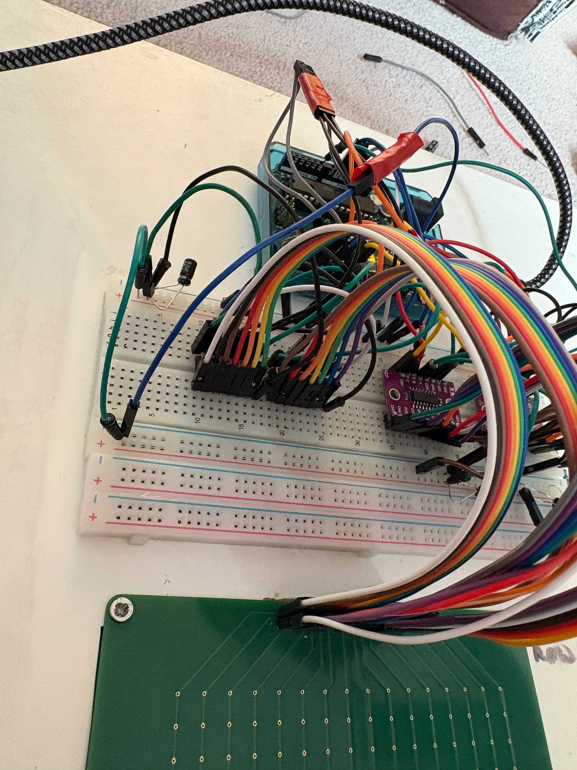
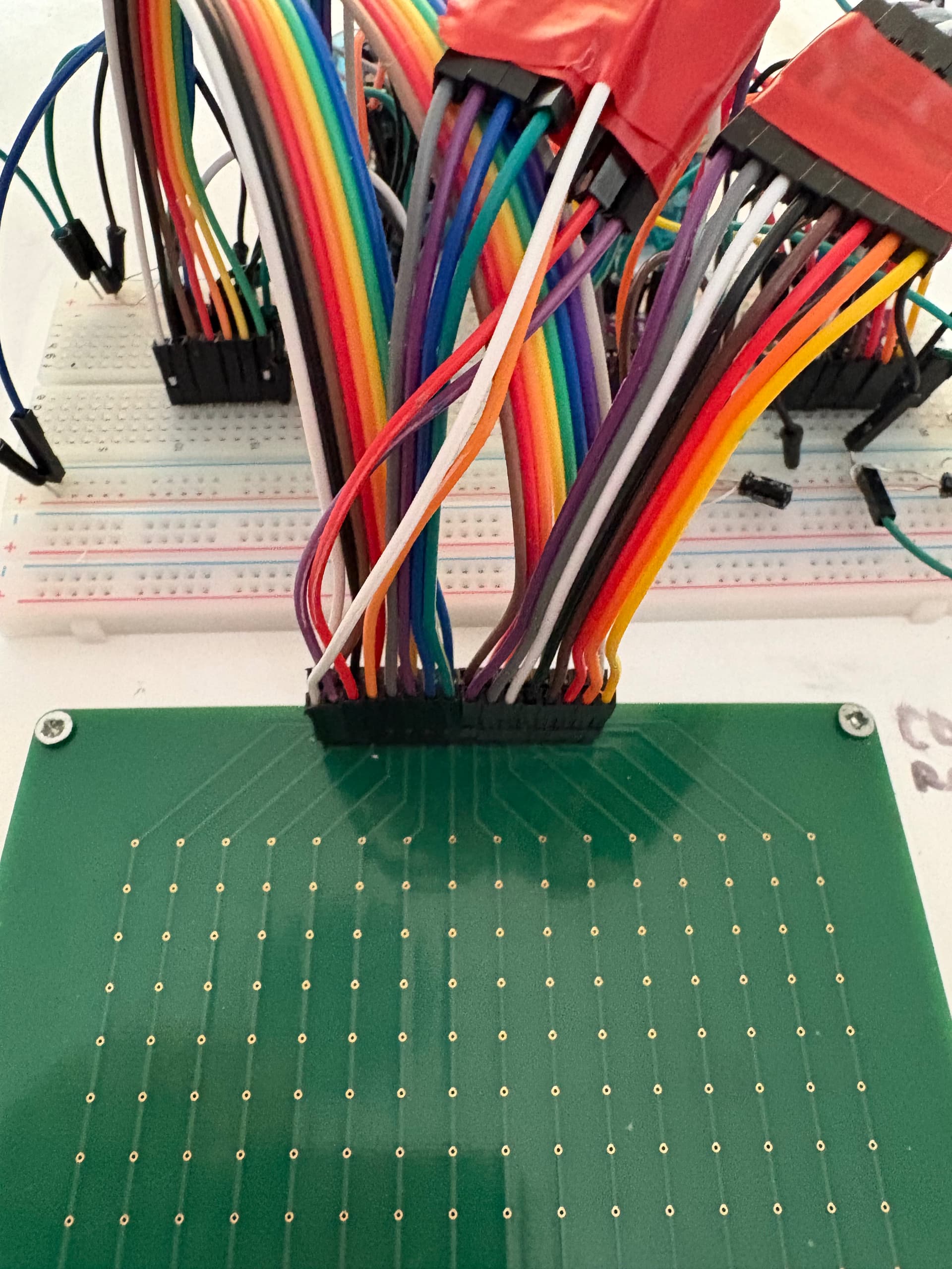
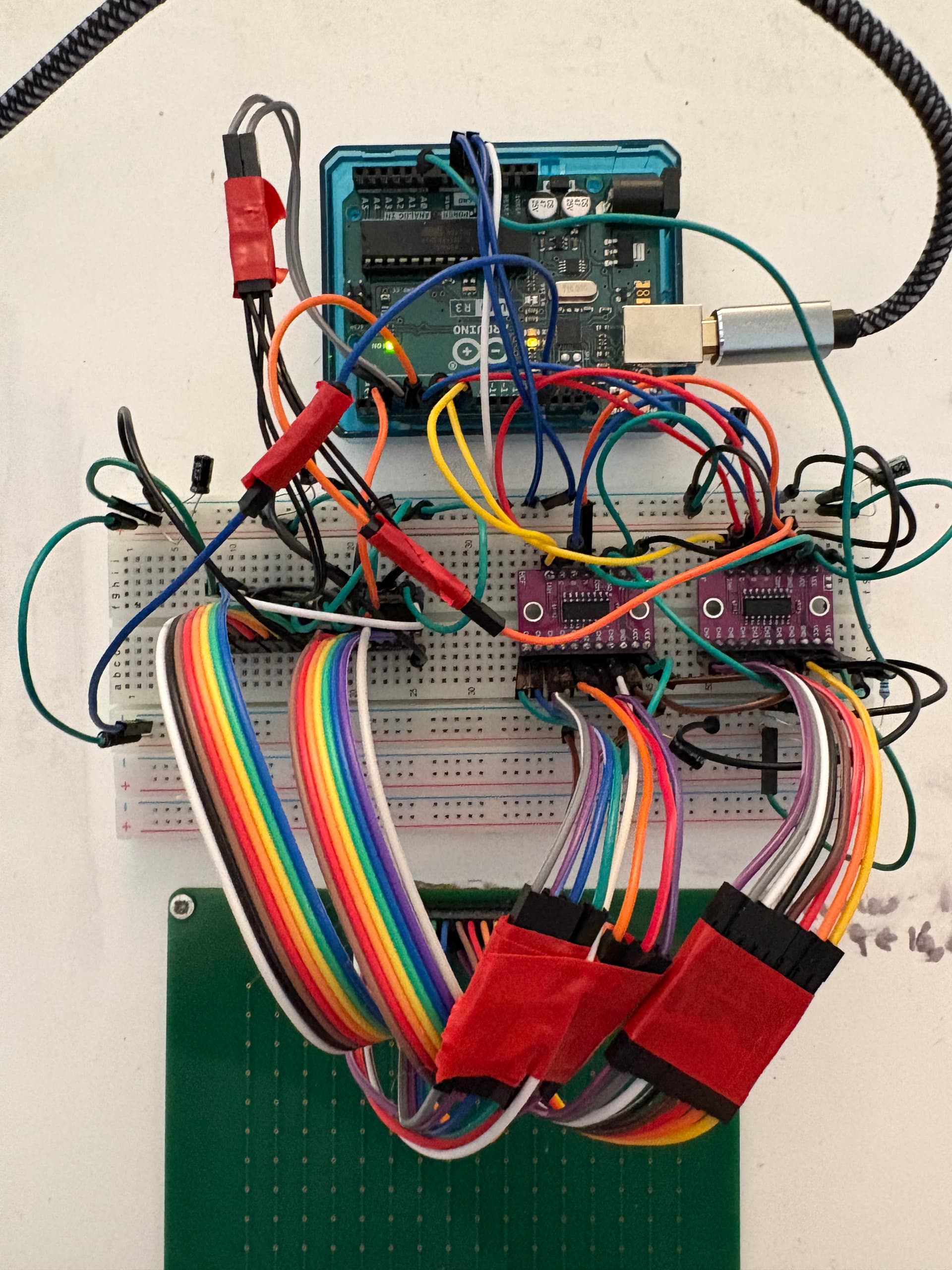
I want to use a Shunt Matrix Array FSR that I have bought and built using the instructions on this website thats for a Thru Matrix Array Tutorials: FSR MatrixArray
It says it can be adjusted but I can't work it out and I am going round in circles! Can anyone help?
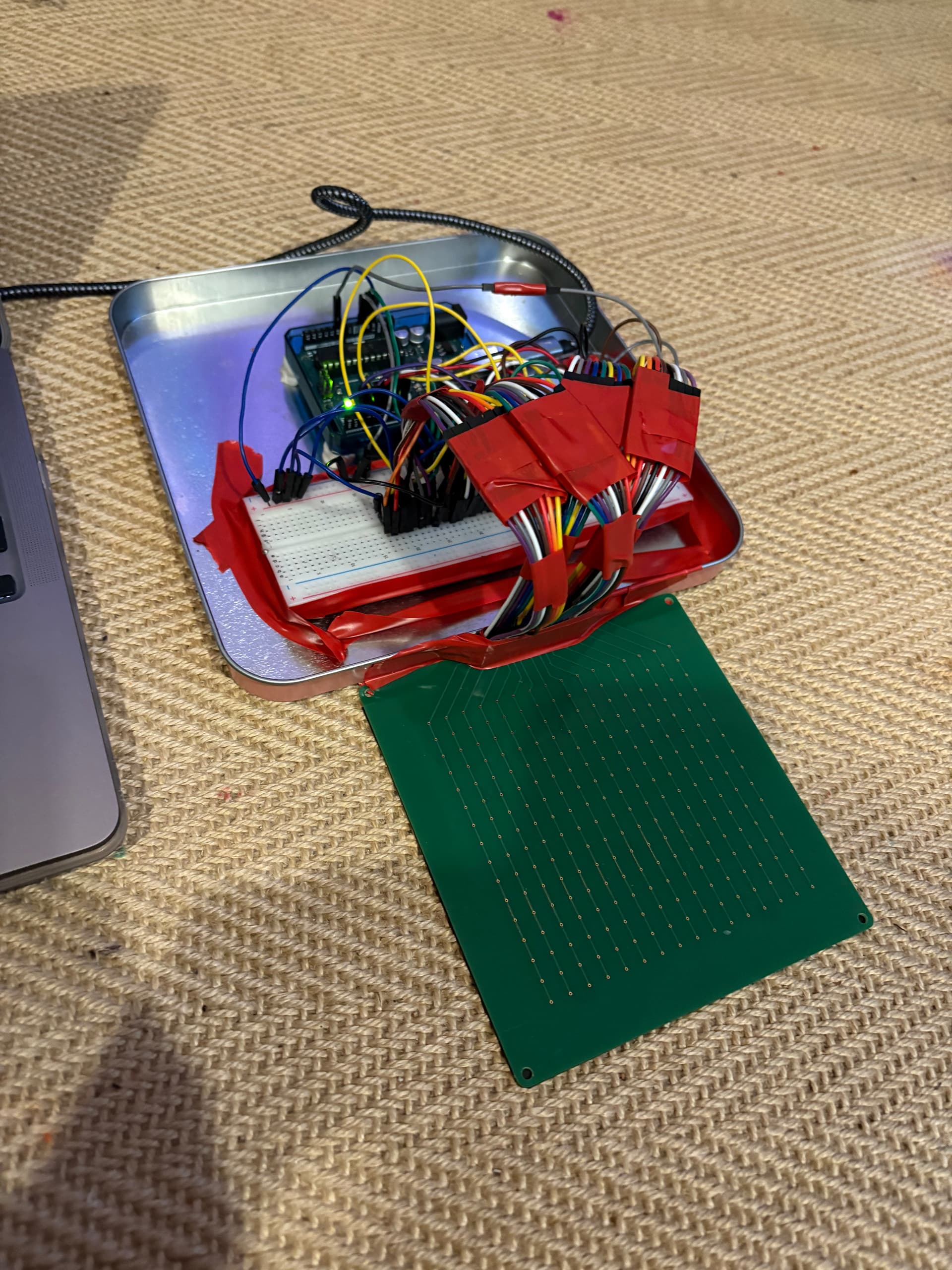
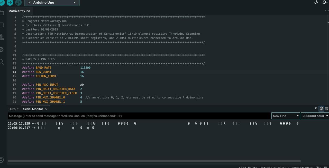
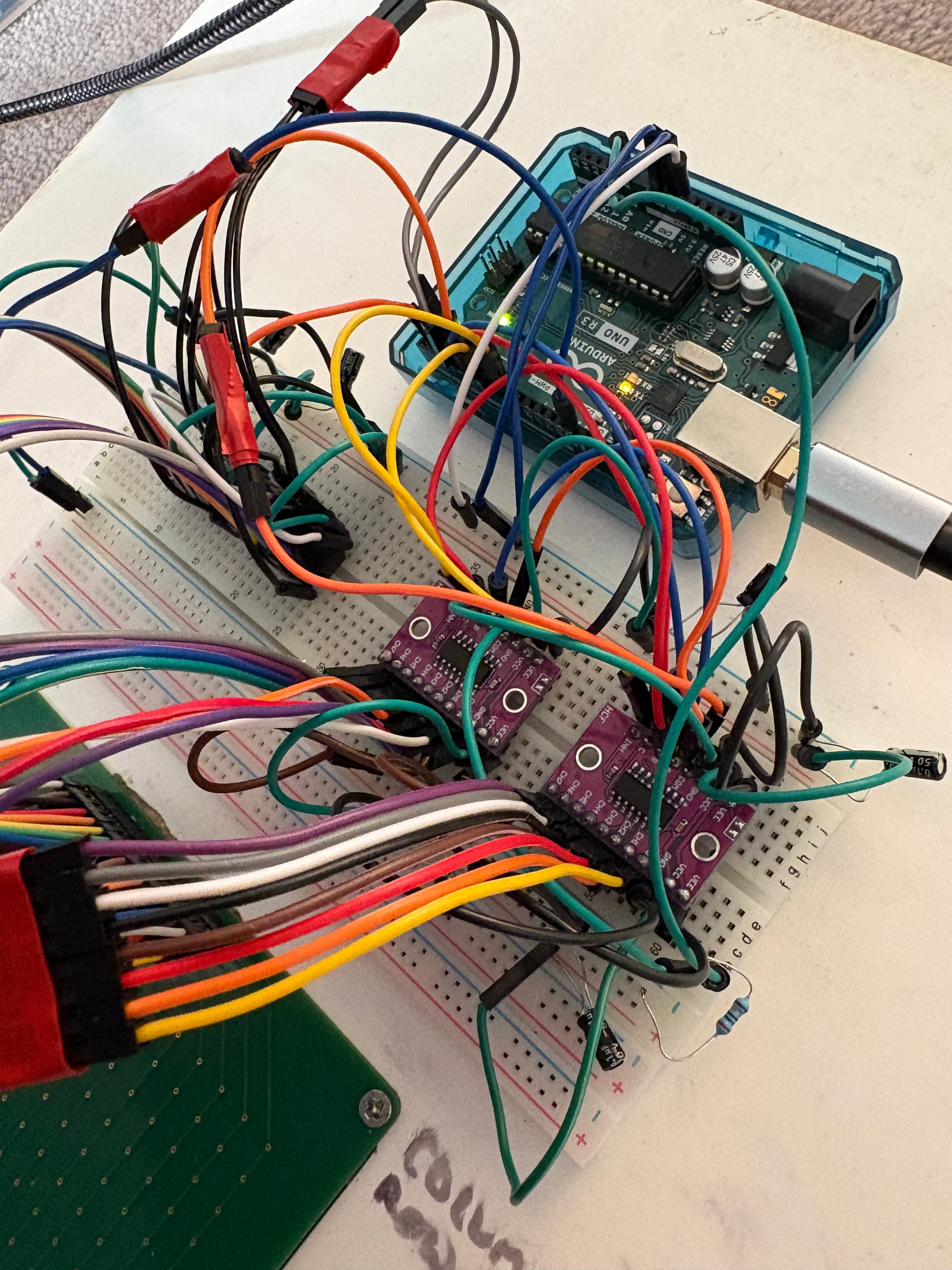
The supplied code is included and the schematic is on the page which I have built my model according to, with the extra rows included on the spare 74HC4051 pins
/**********************************************************************************************************
* Project: MatrixArray.ino
* By: Chris Wittmier @ Sensitronics LLC
* LastRev: 09/09/2015
* Description: FSR MatrixArray Demonstration of Sensitronics' 16x10 element resistive ThruMode. Scanning
* electronics consist of 2 HCT595 shift registers, and 2 4051 multiplexers connected to Arduino Uno.
**********************************************************************************************************/


/**********************************************************************************************************
* MACROS / PIN DEFS
**********************************************************************************************************/
#define BAUD_RATE                 115200
#define ROW_COUNT                 10
#define COLUMN_COUNT              16

#define PIN_ADC_INPUT             A0
#define PIN_SHIFT_REGISTER_DATA   2
#define PIN_SHIFT_REGISTER_CLOCK  3
#define PIN_MUX_CHANNEL_0         4  //channel pins 0, 1, 2, etc must be wired to consecutive Arduino pins
#define PIN_MUX_CHANNEL_1         5
#define PIN_MUX_CHANNEL_2         6
#define PIN_MUX_INHIBIT_0         7  //inhibit = active low enable. All mux IC enables must be wired to consecutive Arduino pins
#define PIN_MUX_INHIBIT_1         8

#define ROWS_PER_MUX              8
#define MUX_COUNT                 2
#define CHANNEL_PINS_PER_MUX      3


/**********************************************************************************************************
* GLOBALS
**********************************************************************************************************/
int current_enabled_mux = MUX_COUNT - 1;  //init to number of last mux so enabled mux increments to first mux on first scan.


/**********************************************************************************************************
* setup()
**********************************************************************************************************/
void setup()
{
  Serial.begin(BAUD_RATE);
  pinMode(PIN_ADC_INPUT, INPUT);
  pinMode(PIN_SHIFT_REGISTER_DATA, OUTPUT);
  pinMode(PIN_SHIFT_REGISTER_CLOCK, OUTPUT);
  pinMode(PIN_MUX_CHANNEL_0, OUTPUT);
  pinMode(PIN_MUX_CHANNEL_1, OUTPUT);
  pinMode(PIN_MUX_CHANNEL_2, OUTPUT);
  pinMode(PIN_MUX_INHIBIT_0, OUTPUT);
  pinMode(PIN_MUX_INHIBIT_1, OUTPUT);
}


/**********************************************************************************************************
* loop()
**********************************************************************************************************/
void loop()
{
  for(int i = 0; i < ROW_COUNT; i ++)
  {
    setRow(i);
    shiftColumn(true);
    shiftColumn(false);                         //with SR clks tied, latched outputs are one clock behind
    for(int j = 0; j < COLUMN_COUNT; j ++)
    {
      int raw_reading = analogRead(PIN_ADC_INPUT);
      byte send_reading = (byte) (lowByte(raw_reading >> 2));
      shiftColumn(false);
      printFixed(send_reading);
      Serial.print(" ");
    }
    Serial.println();
  }
  Serial.println();
  delay(200);
}


/**********************************************************************************************************
* setRow() - Enable single mux IC and channel to read specified matrix row.
**********************************************************************************************************/
void setRow(int row_number)
{
  if((row_number % ROWS_PER_MUX) == 0)  //We've reached channel 0 of a mux IC, so disable the previous mux IC, and enable the next mux IC
  {
    digitalWrite(PIN_MUX_INHIBIT_0 + current_enabled_mux, HIGH);  //Muxes are enabled using offset from MUX_INHIBIT_0. This is why mux inhibits MUST be wired to consecutive Arduino pins!
    current_enabled_mux ++;
    if(current_enabled_mux >= MUX_COUNT)
    {
      current_enabled_mux = 0;
    }
    digitalWrite(PIN_MUX_INHIBIT_0 + current_enabled_mux, LOW);  //enable the next mux, active low
  }
  for(int i = 0; i < CHANNEL_PINS_PER_MUX; i ++)
  {
    if(bitRead(row_number, i))
    {
      digitalWrite(PIN_MUX_CHANNEL_0 + i, HIGH);
    }
    else
    {
      digitalWrite(PIN_MUX_CHANNEL_0 + i, LOW);
    }
  }
}


/**********************************************************************************************************
* shiftColumn() - Shift out a high bit to drive first column, or increment column by shifting out a low
* bit to roll high bit through cascaded shift register outputs.
**********************************************************************************************************/
void shiftColumn(boolean is_first)
{
  if(is_first)
  {
    digitalWrite(PIN_SHIFT_REGISTER_DATA, HIGH);
  }
  digitalWrite(PIN_SHIFT_REGISTER_CLOCK, HIGH);
  digitalWrite(PIN_SHIFT_REGISTER_CLOCK, LOW);
  if(is_first)
  {
    digitalWrite(PIN_SHIFT_REGISTER_DATA, LOW);
  }
}


/**********************************************************************************************************
* printFixed() - print a value padded with leading spaces such that the value always occupies a fixed
* number of characters / space in the output terminal.
**********************************************************************************************************/
void printFixed(byte value)
{
  if(value < 10)
  {
    Serial.print("  ");
  }
  else if(value < 100)
  {
    Serial.print(" ");
  }
  Serial.print(value);
}