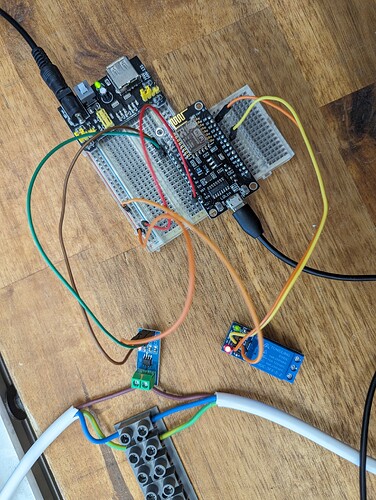
Hi, I am having issues whereby a turning on a digital output (to a relay) is affecting the input analogue signal on the A0 pin.
It is for an automated power board that reads the current off one mains line (a power tool) and activates a relay (a vacuum) for dust collection. The project and code is somewhat based off this project
(https://www.instructables.com/Automatic-Load-Vacuum-Switch-With-ACS712-and-Ardui/)
The acs module is working and detects the voltage a current off the tool line appropriately, however as soon as the relay is activated the analogue signal from the ACS goes haywire. Subsequently the relay never turns off as it remains above the threshold to turn it on
Disconnecting the relay returns the analogue signal to normal working order
The analogue signal coming out of the A0 pin is as follows: (0-1024)
Relay off, no load: 806min - 811 max (0.71 watts)
Relay off with load from tool: 788-832 (160 watts)
Relay on - 480-830 (1425 watts)
Other points
- Both relay and ACS module are powered off an external 5V supply (breadboard adapter)
- I have considered "ground bounce" as an issue and tried separating the ground lines from each component to the mcu but no help [Switching relay on and off affects analog sensor output voltage - Electrical Engineering Stack Exchange]
- ACS712 20A unit
- Esp8266 NodeMCU
- Tongling 5V relay off aliexpress
- The code has a 5 second delay, built in to turn the relay off 5 seconds after the tool line current is turned off
Any ideas what is causing this ?!?!?!
(Sorry Im not great with schematics yet, but hopefully its a simple enough circuit for the pic to suffice)
Code:
#define inputPin A0       //ACS712 analog input pin
#define relayPin 5        //Control relay output pin GPIO 5 = D1 on esp8266

//const int sensorIn = A0;
int mVperAmp = 100; // use 185 for 5A, 100 for 20A Module and 66 for 30A Module

double Voltage = 0;
double VRMS = 0;
double AmpsRMS = 0;

unsigned long previousMillis = 0;
unsigned long currentMillis = 0;

//Turn off delay after tool stops 1000 = 1 second
const long interval = 5000;

void setup(){
  pinMode(A0, INPUT);
  pinMode(relayPin, OUTPUT);
  //digitalWrite(relayPin, LOW);
  Serial.begin(115200);
  delay(10);
  Serial.println(F("Init...."));
}

void loop(){
  Voltage = getVPP();
  VRMS = (Voltage/2.0) *0.707; // sq root
  AmpsRMS = (VRMS * 1000)/mVperAmp;
  float Wattage = (240*AmpsRMS)-20; //Observed 18-20 Watt when no load was connected, so substracting offset value to get real consumption.
  Serial.print(AmpsRMS);
  Serial.print(" AmpsRMS      ");
  Serial.print(Wattage);
  Serial.println(" Watts ");

  if (Wattage > 50) {
  digitalWrite(relayPin, HIGH);
  Serial.println("Relay On");
  previousMillis = millis();
  } else {
  currentMillis = millis();
  if (currentMillis - previousMillis >= interval) {
    previousMillis = currentMillis;
    digitalWrite(relayPin, LOW); }
  }
}

float getVPP()
{
  float result;

  int readValue;             //value read from the sensor
  int maxValue = 0;          // store max value here
  int minValue = 1024;          // store min value here

   uint32_t start_time = millis();

   while((millis()-start_time) < 1000) //sample for 1 Sec
   {
       readValue = analogRead(inputPin);
       // see if you have a new maxValue
       if (readValue > maxValue)
       {
           /*record the maximum sensor value*/
           maxValue = readValue;
       }
       if (readValue < minValue)
       {
           /*record the maximum sensor value*/
           minValue = readValue;
       }
    }

   // Subtract min from max
   result = ((maxValue - minValue) * 5)/1024.0;

   return result;
 }
